Uneven screw wear is a reason to investigate alignment, not proof that alignment is the only fault. Compare the damage pattern with component measurements, the drive-to-barrel reference and the machine's thermal condition before replacing parts. A new screw can match its drawing yet still encounter the installation or process condition that damaged the previous one.
- Record the location and shape of damage before polishing away evidence.
- Separate abrasive wear, solids wedging and alignment-related contact.
- Check component geometry and installed alignment as different tasks.
- Use a defined drive reference; a level machine frame is not an alignment report.
- Accept the repair on documented checks and a controlled return to production.
Does uneven wear prove a single-screw extruder is misaligned?
No. A wear pattern tells you where to look next, while measurements and operating history help establish the cause. Begin by identifying what changed: the component, barrel supports, heaters, material, production rate or maintenance work. A defect that appeared after installation deserves a different investigation from gradual wear under an unchanged duty.
The most useful first distinction is between a performance signal and direct evidence of component condition. Lower output or higher melt temperature can justify investigation, but neither identifies a bent screw or an offset barrel by itself. In their extrusion wear analysis, Tim Womer and Mark Spalding discuss specific output and discharge temperature alongside several wear mechanisms, including fillers, solids wedging and poor alignment.
| Finding | What it supports | What remains to be checked |
|---|---|---|
| Output falls at a comparable operating point | The process no longer matches its baseline | Feed, material, restriction, temperature and component condition |
| An exposed screw has local contact damage | Contact occurred at an identified location | Component geometry, installation and process-related side loading |
| Bore dimensions differ from the original record | The installed barrel needs dimensional assessment | Whether the bore axis and drive reference also agree |
| Problems appear after a barrel or support change | Recent work is relevant to the investigation | Installation records and the actual alignment result |
| Cold checks look acceptable but a problem appears after heating | Thermal condition belongs in the review | Support movement, heating balance and the machine supplier's specified hot-state checks |
Keep the operating comparison fair. Record the resin grade, feed mode, rpm, measured output, melt temperature and restriction configuration. A pressure or current change measured after several other changes is not a diagnosis. Do not assign a universal percentage drop as proof of wear or misalignment.
This guide concerns single-screw extruder alignment and uneven contact. It does not cover the timing or intermeshing-clearance checks of a twin-screw assembly. For wear-rate tracking and planned replacement intervals, use the EJS screw barrel service-life guide.
Read the wear pattern before changing the hardware
Inspect the screw after cleaning by the approved method, but photograph damage before removing burrs or changing its appearance. Mark the axial position from a named reference end. Take a wider location photograph and a close-up so another person can find the same feature on the drawing.
Jim Frankland's comparison of wedging and misalignment explains why these causes can be confused. In his observations, solids wedging can produce a burr on the trailing edge of a flight; alignment-related crushing can affect both leading and trailing edges. He also notes that the mechanisms can coexist. Treat these as inspection clues rather than a stand-alone acceptance test.
| Pattern to document | Investigation it raises | Evidence needed beyond appearance |
|---|---|---|
| Burr concentrated on a trailing flight edge | Possible solids wedging | Axial location, melting conditions, material history and complete profile |
| Damage to both flight edges or visibly crushed lands | Possible alignment-related contact | Screw condition, bore condition and a referenced alignment survey |
| Rounded lands and gradual diameter loss | Wear affecting working geometry | A repeatable OD/ID measurement map and material-duty history |
| A localized gouge or isolated impact mark | A separate damage event may be involved | Contamination, extraction and maintenance history |
Solids wedging is not simply another name for an offset barrel. Frankland describes unmelted material obstructing a channel and creating an unbalanced radial force. Its location and the melting arrangement matter to the review. A more wear-resistant surface cannot establish whether the geometry or operating conditions generated that loading. The EJS barrier-versus-conventional screw guide explains how to separate melting and mixing questions when reviewing that profile.
Use consistent labels for leading and trailing edges, tied to the drawing and specified rotation. Avoid annotating an isolated photograph with an assumed direction. Likewise, define a fixed clock reference for the stationary barrel and a separate identifying reference for the removed screw; a rotating component's position must not be casually equated with a fixed side of the machine.
The EJS materials guide supports the separate question of surface selection. Decide whether the task is restoring worn geometry, changing the working surface or correcting a loading condition before asking an alloy change to solve everything.
Leveling is not screw-and-barrel alignment
A level checks an orientation relative to gravity. An alignment survey checks specified features against a defined reference. A machine frame can be level while the processing components do not share the required axis.
Davis-Standard identifies the gearbox drive quill as the reference for its extruder alignment procedure. It describes establishing that reference with optical or laser equipment, then relating the barrel and feed throat to it. The relevant lesson is to identify the machine manufacturer's datum and method, rather than substitute a spirit-level reading for an axis survey.
Ask what the alignment report actually measures
A usable report names the machine and components, reference feature, measurement stations, coordinate convention and thermal state. It identifies the instrument and records results before and after any authorized adjustment. A statement that the extruder was "checked" leaves these questions unanswered.
Ask whether a reported result concerns the drive reference, feed throat, barrel bore or another feature. The outside surface of a component, its flange face and its internal bore are not interchangeable references unless the specified method establishes their relationship. The technician should explain which feature was used and why it represents the required axis.
Level frame ≠ aligned barrel axis
Conceptual axis relationships; offsets exaggerated.
A. Different axis relationships
Barrel axis
Drive datum
Level frame
The frame is level, but the axis references differ.
B. Axis relationship checked to the drive datum
Barrel axis and drive datum coincide in this conceptual view.
Level frame
Legend: solid orange = barrel axis; dashed black = drive datum.
Not a support design, field adjustment or acceptance limit.
Do not adjust supports from a photograph or a sketch. The approved method determines which checks and adjustments are possible for that machine. Keep the mechanical survey separate from downstream die or haul-off alignment, which addresses a different relationship.
The EJS extruder screw barrel buyer's guide explains the component information needed for a replacement specification. Keep that specification connected to the installation report, rather than assume a new part provides its own alignment reference.
Separate straightness, runout, bore size and alignment
These terms should not appear as interchangeable entries in an inspection report. Bore size describes a dimension at a location. Straightness concerns the geometry of a specified feature. Runout is a measured variation relative to a rotation reference and setup. Installed alignment concerns the relationship between specified components or axes.
| Check | Question it answers | Information needed with the result |
|---|---|---|
| Screw OD and barrel ID | What are the working diameters at this station? | Position, directions measured, instrument and temperature condition |
| Component straightness | Does the specified feature meet its geometric requirement? | Feature, evaluation length, support/setup and drawing callout |
| Runout | What variation is observed relative to the stated rotation reference? | Datum/setup, contact location and reported reading convention |
| Installed alignment | How does the barrel relationship compare with the specified machine reference? | Datum, stations, thermal state and machine acceptance requirement |
What the EJS straightness figure does and does not mean
The EJS quality-inspection guide lists 0.015 mm under straightness and identifies a dial-indicator setup on centers or V-blocks. Read that as a component inspection item in its published context. It is not a universal permissible drive-to-barrel offset for every extruder.
For an order or condition assessment, identify the actual drawing requirement, feature and evaluation method. An indicator reading without its reference and support condition cannot be relabeled as installed alignment. Nor should a total indicator reading be converted into a centerline offset without knowing what geometry the setup measures.
Keep temperature conditions explicit. If a new-part report, removed-part measurement and installed survey were taken in different conditions, preserve those differences in the records. Comparing the numbers without their setup can make a sound component look suspect or conceal a real installation issue.
Do not invent an alignment tolerance from nominal screw diameter or an unrelated straightness value. The required relationship comes from the machine specification; the component drawing supplies a different set of requirements.
A clearance example: why correct diameters do not prove centering
An OD/ID comparison is necessary, but it cannot establish where a screw sits relative to a barrel axis. A simple circular-section example shows the distinction without assigning a manufacturing tolerance.
Assume a perfectly round barrel bore of 100.12 mm and a perfectly round screw-flight envelope of 100.00 mm at one cross-section. If concentric, the radial gap is:
c = (barrel ID − screw-flight OD) / 2 = (100.12 − 100.00) / 2 = 0.06 mm
Now assume the screw-section center is offset by 0.04 mm, while both diameters remain unchanged. Along the line joining the centers, the near-side gap is 0.02 mm and the opposite gap is 0.10 mm.
| Idealized condition | Near-side radial gap | Opposite radial gap |
|---|---|---|
| Concentric sections | 0.06 mm | 0.06 mm |
| Center offset of 0.04 mm | 0.06 − 0.04 = 0.02 mm | 0.06 + 0.04 = 0.10 mm |
The mean of those opposing gaps remains 0.06 mm. A diameter-based clearance calculation therefore does not reveal that local asymmetry. It answers a dimensional question, not the complete alignment question.
Same diameters. Different local gaps.
Ideal circular cross-sections. Gaps and center offset are exaggerated.
Assumed dimensions
| Bore ID | 100.12 mm |
|---|---|
| Flight-envelope OD | 100.00 mm |
| Nominal radial gap c | (100.12 − 100.00) / 2 = 0.06 mm |
A. Concentric
| First side gap | 0.06 mm |
|---|---|
| Opposite side gap | 0.06 mm |
B. Offset center
Assumed center offset e = 0.04 mm.
| Far-side gap c + e | 0.06 + 0.04 = 0.10 mm |
|---|---|
| Near-side gap c − e | 0.06 − 0.04 = 0.02 mm |
The mean of the opposing gaps is still 0.06 mm.
Arithmetic only: not EJS dimensions or a running-clearance limit.
One section only; excludes heat, deflection, nonroundness and process loading.
This model excludes thermal growth, elastic deflection, nonroundness, actual flight geometry and process loading. It also describes one cross-section, not the complete screw length. Use it to understand why the inspection needs both component dimensions and a referenced installation assessment, not to calculate a field adjustment.
Long-barrel alignment: supports, heating and thermal movement
A long barrel review needs more than a cold position check. Davis-Standard's alignment article emphasizes allowing thermal expansion through the support system and checking for deflection after heat-up. It also identifies uneven heating and support problems as possible contributors. Use the machine supplier's support design and thermal-check procedure rather than changing restraints or adding shims by intuition.
Build a record that separates the initial condition from the operating-temperature condition. Record the defined temperature state, support arrangement, machine changes and observations from the authorized inspection. Do not assume every zone reaches the same condition merely because controller setpoints match.
Review what changed around the barrel
Useful questions include:
- Was the barrel, feed throat, gearbox interface or a support moved or replaced?
- Was any support restrained differently during maintenance?
- Were heaters, cooling equipment, insulation or temperature sensors changed?
- Did foundation work or another installation change occur?
- Is the reported condition cold, heating, thermally stabilized or cooling down?
Photographs can document the arrangement but do not measure internal alignment. Compare them with the machine drawings and service findings. The technician needs to identify the relevant positions and movement, not just say that the supports look secure.
Separate observation from intervention. An authorized inspection may involve controlled heating or positioning, while access, component removal and adjustment require the machine's specified energy-control arrangements. Do not open guards, reach around moving components or alter supports during operation to test a theory.
If heating changes the survey result, retain both records and ask which part of the machine system explains the change. A cold-only pass is not a substitute for the thermal assessment required by the machine supplier. Equally, a temperature-related symptom alone does not prove that a support is the cause.
Build an inspection sequence before ordering replacement parts
Begin with the machine's safe operating and maintenance procedures. Noise, abnormal load or suspected contact should be handled through the specified fault response, not a trial designed to make the symptom worse. Do not run an empty screw as an improvised contact test.
For a planned investigation, use a sequence that preserves evidence:
- Save the production baseline and the event history. Identify changes to material, feed, temperature, restrictions and hardware.
- Arrange safe access and cleaning using the equipment's authorized maintenance procedure. Photograph damage before dressing or polishing.
- Map screw and barrel condition at identifiable stations. Keep dimensional readings, photographs and surface observations linked.
- Evaluate the removed screw's geometry using the specified setup. Keep those findings separate from the barrel survey.
- Have a qualified technician assess the installed relationship against the machine reference, including the thermal conditions the manufacturer requires.
- Review the combined findings before deciding on component repair, replacement, machine correction or a process/design investigation.
A compact evidence sheet
| Record | Details that make it usable |
|---|---|
| Component identity | Machine reference, part marking and drawing revision |
| Station map | Named reference end, axial distance and station identifier |
| Screw and barrel measurements | Matching locations, directions, instruments and thermal condition |
| Damage photographs | Wider location view, close-up and a defined orientation reference |
| Component geometry report | Setup, support points, measured feature and results |
| Installed survey | Drive datum, stations, thermal state and before/after findings |
| Process comparison | Resin/feed condition, output, rpm, melt temperature, pressure/load and product checks |
If an independent service provider performs the survey, request the datum, method, thermal state and acceptance criteria before commissioning the work. A quoted "extruder alignment service" needs a defined scope: it may not include screw geometry, a full bore-condition assessment or a hot-state check.
A borescope can document an accessible surface. It does not by itself establish a bore centerline or quantify the whole assembly's working clearance. Keep visual inspection, dimensional measurement and alignment surveying as separate entries in the evidence sheet.
The EJS factory perspective: connect the part report with the machine report
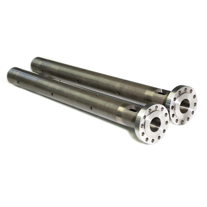
At EJS, we recommend reviewing the approved drawing, actual component measurements and machine findings together when a replacement follows unusual wear. The EJS single screw barrel page describes customized components, dimensional checks and retained quality records. Our extruder screw barrel product page also identifies the inspection report and material certificate supplied with the parts.
Those documents serve different purposes. A material certificate identifies the supplied material. A dimensional report records the component condition against its specification. Neither establishes the current axis relationship inside the customer's installed machine.
What to send for an uneven-wear component review
Send the machine model, part identification and drawing revision first. Add the wear map, original inspection report if available, current OD/ID readings and photographs tied to positions. Include any component straightness/runout report and the qualified technician's machine survey. Identify whether the proposed replacement will run inside the existing barrel.
If only one component is being replaced, the mating component still belongs in the assessment. A new screw drawing describes the new screw; it does not describe the present condition of a reused bore. State which measurements are original, current or assumed so the quotation is based on the actual assembly.
Keep the required corrections separate in the purchase and maintenance records. An alloy change, a revised melting profile and an alignment correction are different actions. If more than one is required, record why each is being made and how it will be checked. This makes the eventual production comparison useful instead of attributing every improvement to the replacement screw.
Verify the correction before accepting the restart
Completion of an adjustment or installation is one milestone; return to stable, acceptable production is another. Close the mechanical work through the machine's approved release procedure, restore guards and document the accepted configuration before commissioning.
Retain the component acceptance records and the installed survey result. If thermal checks are required, include the specified operating-temperature assessment rather than attach only the cold report. Set the production comparison against a defined material and operating point, and note every intentional change from the earlier baseline.
Specific output can help describe a comparable run:
Specific output = measured mass output (kg/h) / screw speed (rpm)
Report the feed mode, restriction arrangement, melt temperature, pressure/load readings and product results alongside it. A higher mass rate caused only by increasing rpm does not isolate an alignment improvement, and a specific-output change does not prove which mechanical fault existed.
Agree on the required production range and the machine's limits before the trial. Do not seek an arbitrary speed increase to demonstrate success. If the old symptom returns, preserve the new records and compare the findings rather than repeatedly changing settings until the defect is temporarily hidden.
Use the EJS contact page for a component review and send the drawing, measurement map and machine findings together. For service-life planning after the condition has been resolved, establish a fresh baseline and continue the same inspection locations.
Frequently asked questions
Does a level extruder prove the screw and barrel are aligned?
No. Leveling checks orientation relative to gravity. Alignment needs the specified machine reference and a suitable measurement method. Ask the report to identify the datum and measured features rather than accept a frame-level reading as proof of bore alignment.
Does a burr on both flight edges confirm misalignment?
It is a relevant inspection clue, not confirmation by itself. Document the damage and its location, then compare component geometry, bore condition, the installed survey and operating history. More than one wear mechanism may be present.
Can correct screw OD and barrel ID rule out contact?
No. The diameters do not establish centering, full-length geometry, hot-state behavior or process loading. Matching dimensional records are part of the assessment, not a replacement for a referenced machine inspection.
Can a harder alloy solve alignment-related wear?
An alloy change does not establish or correct the machine's axis relationship. Determine whether the problem involves material duty, component damage, installation or process loading, then specify the appropriate action for each finding.
Should an alignment contractor also inspect the screw?
Confirm the scope in advance. Ask whether the work includes removed-screw geometry, bore dimensions and condition, the drive-to-barrel survey and required thermal checks. Different reports answer different questions, even when one provider offers several services.