QUICK ANSWER
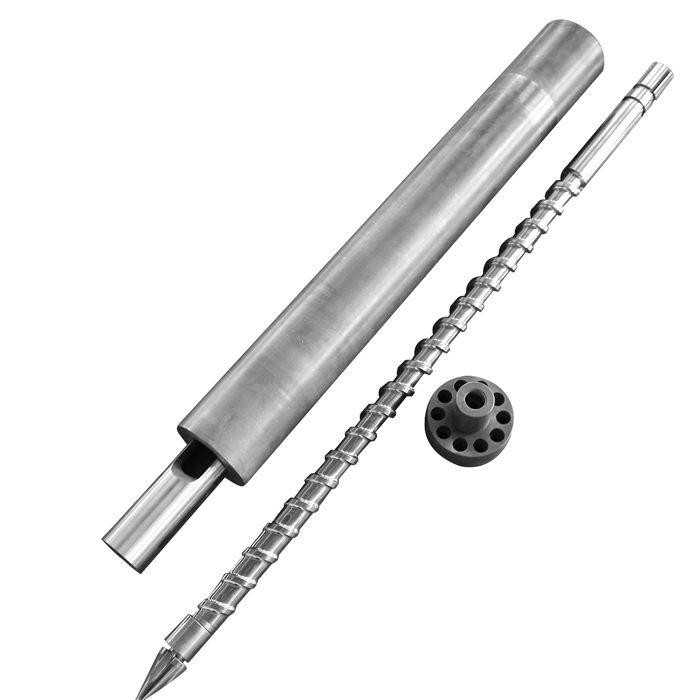
Choose injection molding screws by checking the complete shot requirement against the installed injection unit's volume, pressure and plasticizing capability. Diameter alone cannot settle the choice. A larger screw can provide more volume while reducing the available injection pressure in a given machine configuration.
A request for more shot capacity can lead to the wrong replacement if the problem is actually slow recovery, an incorrect shot-weight calculation or wear in a mating component. Start with the current injection-unit code, the resin and the total material injected per cycle. Then decide whether the job is restoring the existing design or changing the machine configuration.
This guide focuses on that replacement decision. For the broader product overview, see the EJS injection molding screw-and-barrel guide.
1. What is the shot capacity of an injection molding machine?
Shot capacity describes the injection unit's stated maximum delivery capacity under its specified rating basis. It may be expressed as a calculated volume in cm³ or a reference shot weight in grams of polystyrene (g PS). Your required shot size is the material needed for a particular molding cycle.
| Quantity | Typical unit | What to verify |
|---|---|---|
| Theoretical stroke volume | cm³ | Screw diameter and maximum allowed axial stroke |
| Reference shot weight | g PS | The OEM's reference material and rating basis |
| Required total shot | g/cycle | All cavities plus the sprue and runners discharged each cycle |
| Plasticizing demand | kg/h | Material required within the actual recovery window |
Maximum capacity and usable capacity are different
The geometric maximum does not define a suitable operating window for every resin. Allow for the actual process, the OEM's stroke limits and the required cushion. Cushion is a screw-position observation associated with material remaining ahead of the screw at a defined point in the cycle; specify whether you mean minimum cushion or the position at the end of hold.
Keep the rating, the controller setting and the measured total shot on separate lines in the review sheet. That prevents a reference value from quietly becoming an acceptance criterion.
2. How do screw diameter and stroke determine injection volume?
For an ideal cylindrical displacement, multiply the screw's cross-sectional area by the axial stroke. With diameter and stroke in millimeters, divide by 1,000 to convert mm³ to cm³:
V = π × D² × S ÷ 4,000
V = swept volume in cm³ · D = screw diameter in mm · S = axial stroke in mm
πD² ÷ 4
Diameter D
front
Conceptual displacement only. Screw flights, valve movement and actual clearances are not depicted.
Use the correct stroke definition
Maximum stroke, metering position, decompression movement and actual forward travel are different quantities. Establish the machine's position reference before subtracting displayed values. Valve closure, melt compression and leakage can also separate ideal displacement from the material that reaches the mold.
Screw L/D describes working length relative to diameter. It is not the injection stroke and cannot replace S in the volume calculation. Overall part length is another dimension again.
3. Why can a larger screw provide more volume but less pressure?
Under the simplified condition of equal axial injection force, plastic pressure is approximately force divided by screw area: p ≈ F/A. Increasing diameter increases area, so the same force produces less pressure. Actual machine limits depend on the drive and the specified injection-unit configuration.
Read a real injection-unit table
The following values come from ARBURG's ALLROUNDER 470 C GOLDEN EDITION technical data, injection unit 400, printed page 3. They illustrate OEM options, not EJS replacement specifications.
| Screw diameter | Max. stroke | Calculated volume | Max. shot weight | Max. injection pressure |
|---|---|---|---|---|
| 35 mm | 160 mm | 154 cm³ | 141 g PS | 2,500 bar |
| 40 mm | 160 mm | 201 cm³ | 184 g PS | 2,000 bar |
| 45 mm | 160 mm | 254 cm³ | 232 g PS | 1,580 bar |
Source: ARBURG original technical data, page 3. The manufacturer notes that specifications depend on configuration, process and material, and maximum injection pressure and flow may be mutually exclusive.
Compare the pressure and injection rate available at your required operating point. A table containing several maximum values does not promise that the machine can deliver all of them simultaneously.
Clamp tonnage does not identify the screw
Even in large tonnage injection molding, clamp force alone cannot identify the installed injection unit. Record the unit code, current screw diameter and machine documentation. A machine with the same clamp rating may have a different screw, drive or stroke option.
4. How do cavities, sprues and runners affect required shot volume?
Calculate the material discharged into the complete molding system each cycle. For a conventional cold runner mold, the starting mass balance is:
Total shot mass = part mass × cavity count + discharged sprue and runner mass
What is a sprue in injection molding?
The sprue is the main passage carrying melt from the nozzle into the mold's feed system; the solidified material from that passage is also called the sprue. In a cold runner mold, weigh it with the runners when determining the total shot. Record whether the stated part weight is trimmed net weight or includes any attached feed material.
Single-cavity molds require one cavity's part mass; multi-cavity molds require the sum of all cavities. Keep the weighing method consistent, and count each discharged item once.
Hot runner vs cold runner: count the right material
A cold runner system ejects its solidified feed material with each cycle. A hot runner retains molten material in its heated channels, so its entire internal inventory is not added to shot weight on every cycle. The retained material still matters when assessing thermal history and residence time.
Convert mass using a defined material basis
For a volume estimate, use V = m/ρ with an appropriate melt density, or the OEM's documented material conversion method. Record the resin grade and the basis of the value. Bulk pellet density and room-temperature solid density are not interchangeable with density at processing conditions.
Use material-specific capacity guidance
Celanese recommends shots of 30% to 70% of maximum machine capacity for its Celcon and Hostaform acetal families, while its Vectra LCP guidance gives 50% to 75%. Those are material-family recommendations intended to manage residence time, not a universal acceptance range for every resin. See Celanese's standard injection molding guidance.
Define the numerator and denominator before calculating utilization. Total shot volume divided by theoretical maximum volume is a geometric ratio. It does not include every dynamic effect or automatically satisfy a material supplier's processing recommendation.
5. A worked example: compare 40 mm and 45 mm screw options
For this example, I start with a hypothetical total shot of 72 g, including all material discharged each cycle, and assume a melt density of 0.80 g/cm³. The density is a calculation input, not a specified resin grade. Required melt volume is therefore 72 ÷ 0.80 = 90.0 cm³.
I then compare two candidate injection-unit setups with screw diameters of 40 mm and 45 mm, each with an assumed maximum stroke of 160 mm:
| Calculation | 40 mm option | 45 mm option |
|---|---|---|
| Maximum theoretical volume | π × 40² × 160 ÷ 4,000 = 201.1 cm³ | π × 45² × 160 ÷ 4,000 = 254.5 cm³ |
| Required ideal travel | 90 × 4,000 ÷ (π × 40²) = 71.6 mm | 90 × 4,000 ÷ (π × 45²) = 56.6 mm |
| Geometric volume utilization | 90 ÷ 201.1 ≈ 44.8% | 90 ÷ 254.5 ≈ 35.4% |
Both theoretical volumes exceed the example's demand. I would still check pressure capability, resin conditions, cushion and recovery time before choosing either configuration. A lower utilization percentage alone does not make the larger option better.
These calculations exclude valve-closing displacement, melt compression and leakage. They compare complete candidate configurations; they do not authorize installing a 45 mm screw in a barrel designed for a 40 mm screw.
6. Can the screw plasticize the shot within the available time?
Shot capacity measures how much material a unit can inject. Plasticizing capacity concerns how quickly it can prepare usable melt under the specified conditions. A screw can have enough geometric volume and still take too long to recover.
Calculate demand over the actual recovery window
Continuing the hypothetical 72 g example, a 24-second cycle consumes an average of 72 ÷ 24 × 3.6 = 10.8 kg/h. If the actual time available for plasticizing is only 8 seconds, the required average rate during that window is 72 ÷ 8 × 3.6 = 32.4 kg/h.
Average consumption
10.8 kg/h
Required rate in that window
32.4 kg/h
I would compare the window demand with resin-specific capability and trial records at acceptable melt quality. Raising screw speed without checking material condition can exchange a time problem for a thermal or melt-quality problem.
Residence time needs a separate assessment
Maximum swept volume is not the total material inventory in the barrel, screw channels and front-end passages. Dividing it by shot volume and multiplying by cycle time does not produce a reliable total residence-time measurement.
Assess hold-up, throughput, interruptions and melt temperature together. Celanese's Rynite PET molding guide, in its melt-and-cylinder-temperature discussion, addresses the relationship between shot size, cycle time and residence conditions. Apply the guide for the actual resin grade; PET recommendations are not settings for all plastics.
7. What must match when replacing an injection screw and barrel?
BEFORE SPECIFYING A LARGER SCREW
If I received an inquiry saying, "We need more shot capacity, so we want a larger screw," I would first identify the installed injection unit and separate the material used in each cycle. Along with part weight, I would check cavity count and the cold runner and sprue discharged each cycle. The machine's PS-rated shot weight cannot simply become the available shot weight for another resin.
Next, I would review allowed stroke, pressure margin and the actual plasticizing window. Insufficient volume and slow recovery need different checks: the first concerns usable capacity; the second also requires a review of material, screw geometry and operating conditions. A short shot or slower recovery alone cannot establish that the screw diameter is wrong.
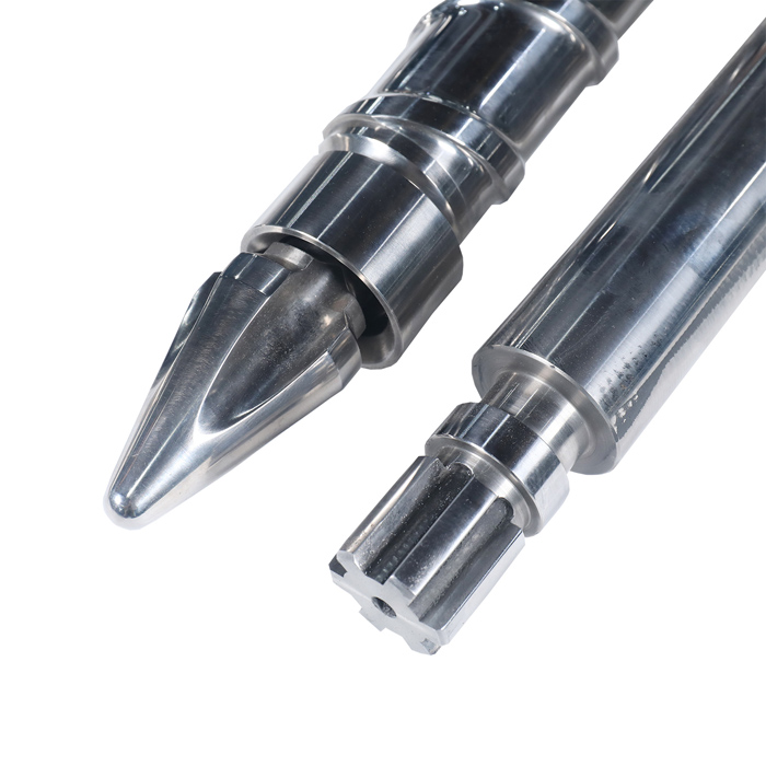
On the replacement drawing, I would check the barrel bore, working length, drive connection, locating shoulder and screw-tip assembly. Worn dimensions from an old part cannot automatically become the nominal dimensions for a new one. My recommendation is to define whether the job restores the existing configuration or changes it, then review diameter and validate the result with the agreed resin and mold.
Make the interface review traceable
| Check | What to record | Evidence to attach |
|---|---|---|
| Machine identity | Model, injection-unit code, current screw option and part numbers | Nameplates, OEM parts list and modification history |
| Screw and barrel | Nominal diameter, matched bore, working and overall lengths | Approved drawing revision and measurement locations |
| Drive and locating features | Spline or key details, coupling, shoulders and axial location | Interface drawing and labeled photographs |
| Front-end assembly | Thread size and direction, mating components and axial envelope | Assembly drawing, parts identification and inspection record |
| Material and treatment | Resin grade, fillers, regrind and agreed component specification | Material data and specified inspection documents |
For every unresolved field, name who will confirm it. Separate nominal new-part dimensions from measurements of worn hardware. If the original drawing is missing, use the OEM identification, labeled measurements and mating parts to establish a reviewable specification.
A diameter change also requires review of the matched barrel, screw tip, drive load, control conversion and OEM-permitted configuration. For valve-component identification, use the EJS screw-tip and check-ring guide.
8. How should a replacement be inspected and validated?
Separate acceptance of the manufactured components from validation of the molding process. A dimensional report answers whether a part meets its agreed specification. A production trial answers whether the installed configuration meets the defined job requirements.
| Stage | Checks | Record and decision basis |
|---|---|---|
| Before shipment | Part identity, drawing revision, dimensions, material and specified treatment | Specified locations, units, methods and agreed drawing limits |
| Before installation | Mating-part condition and confirmation of the approved configuration | Component inspection and machine-specific installation requirements |
| After installation | Representative resin and mold; shot weight, cushion, recovery, pressure and part quality | Recorded settings, consistent measurement methods and agreed acceptance criteria |
Agree sample quantities and pass/fail criteria before the trial. Keep the resin grade, cavity configuration, runner system and measurement method with the results so that later comparisons use the same basis.
Weight variation, cushion movement or longer recovery can justify investigation, but none independently identifies a failed component. Check material preparation, feed conditions, machine settings and the valve's mating parts alongside screw and barrel condition.
9. What should you send EJS for a replacement review?
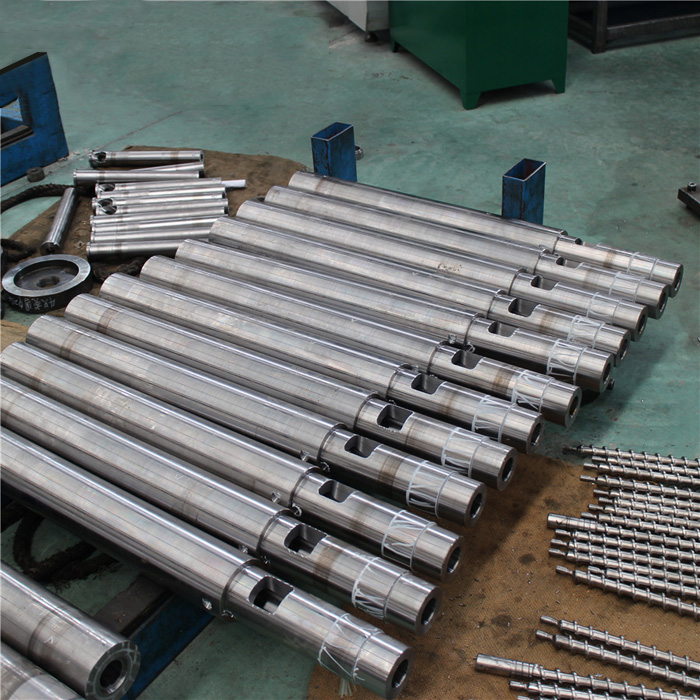
EJS's injection screw barrel product page describes custom work based on the processed material, product requirements and critical connecting dimensions. Prepare the following information so the replacement request defines both the component and its intended job:
- Machine model, injection-unit code, current screw diameter and existing part numbers.
- Current drawings or labeled photographs and measurements of the screw, barrel and mating interfaces.
- Resin grade, filler content, regrind use and the component material or treatment already specified.
- Part weight, cavity count and the sprue/runner mass discharged each cycle.
- Cycle time, actual recovery window, current process records and the problem to resolve.
- A clear objective: restore the existing design or assess a change in capacity or configuration.
EJS states that it supplies inspection reports and material certificates for its screw barrels. Include the required document scope in the order and tie it to the approved part identity and drawing. These records support component acceptance; the application still needs its own agreed process validation.
Discuss the screw and barrel as a matched replacement
Send the machine and component information with your shot and cycle data. Identify any missing fields so they can be resolved before the replacement specification is finalized.
sales@ejsscrewbarrel.com
+86-574-83065911
10. Frequently asked questions
Can a 0.37 lb injection molded part tell me the required machine tonnage or screw diameter?
No. Part weight alone cannot determine either. Clamp sizing also needs projected area and cavity-pressure requirements, while the injection unit needs the complete shot, resin conditions, pressure, injection rate and recovery-time requirements. Include all cavities and the feed material discharged each cycle before assessing screw capacity.
Is PS-rated shot weight the same as the shot weight available for PP?
No. A rating in grams of PS uses a polystyrene reference basis. Use the OEM's documented conversion method or an appropriate material-density basis for the actual PP grade and conditions. Do not substitute a pellet bulk-density value or copy a conversion factor from an unrelated machine.
Is 20% to 80% shot utilization suitable for every material?
No. Capacity guidance depends on the resin, machine and processing conditions, including residence time. Define how utilization is calculated and consult the relevant resin supplier and OEM guidance. A broad percentage range does not replace a grade-specific review.
Can I increase shot capacity by replacing only the screw with a larger one?
A larger diameter requires a compatible barrel and a review of the complete injection-unit configuration. Check the front-end assembly, drive connection, loads, control conversion and OEM limitations. A volume calculation alone does not approve the conversion.
Does a stable cushion prove that the screw and barrel are unworn?
No. Stable cushion is one process observation under defined conditions. It does not establish the dimensions or condition of the screw, barrel and valve components. Use consistent process records alongside the relevant dimensional and component inspections.
What can I provide if the original screw drawing is missing?
Start with the machine and injection-unit identification, existing part numbers, labeled photographs and measurements of the current parts and their mating interfaces. Record worn measurements separately from proposed nominal dimensions. The information must be reviewed into an agreed specification before manufacture.