Choose an injection molding screw tip assembly by its valve design, mating dimensions and resin conditions. A check ring is one component of a ring-type assembly, not a universal name for every screw-tip design. Before ordering a replacement, identify the complete assembly and inspect its mating parts. Cushion or shot-weight variation is a reason to investigate the valve and process together, not proof that the ring alone needs replacing.
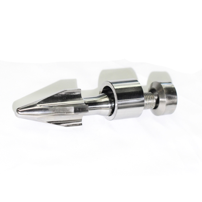
1. How does an injection molding check ring work?
In a typical sliding-ring assembly, the tip or retainer holds the check ring on the screw head. A rear seat provides the mating face for closure. During recovery, the ring is away from that seat so melt can move through the valve and collect ahead of the screw. During injection, the ring and rear seat come together to oppose backflow.
The component names can be confusing. A supplier may use "screw tip" for the pointed retainer or for the complete non-return valve. Ask for a parts view with item numbers before comparing quotations. A ring, a tip and a complete assembly are different order items.
For a ring-type valve, inspect two separate relationships: the ring's mating contact with the rear seat, and its fit within the barrel bore. Neither can be evaluated from the ring's outside diameter alone. John Bozzelli's explanation of non-return valves describes these two sealing relationships.
Typical sliding-ring valve: opening is not the same as sealing
Schematic longitudinal section. Screw-fixed reference; nozzle / mold direction is to the right.
A. RECOVERY: RING OPEN
The check ring is away from the rear seat. The open gap allows melt to pass through the valve.
Left to right: rear seat → open gap → check ring → tip / retainer.
B. INJECTION: RING SEATED
The check ring contacts the rear seat. The valve opposes backflow.
Left to right: rear seat → seat contact with check ring → tip / retainer.
Diagram key: dark gray = rear seat; orange = check ring; light gray = tip / retainer. The upper and lower gray lines represent the barrel.
Check both: ring-to-seat contact and ring-to-barrel fit.
Clearances and passages are exaggerated. Actual profiles and motion must follow the approved design.
Illustration only; not an EJS manufacturing drawing, flow simulation or dimensional specification.
EJS's screw-tip assembly product page lists check valves, ball checks and locking ring assemblies. That range is why a replacement inquiry should identify the valve mechanism rather than request a generic check ring. For the surrounding plasticizing unit, see the injection molding screw-and-barrel guide.

2. Sliding and locking ring valves: what changes?
Valve names describe different aspects of a design. Sliding versus locking concerns the ring's rotational relationship with the screw. Three-piece versus four-piece describes how components are divided. Ball check identifies a different closing element. Those labels are not interchangeable categories.
| Design description | What it identifies | What the buyer should establish |
|---|---|---|
| Sliding-ring valve | A ring that is not positively keyed to rotate with the screw | Ring travel, seat geometry, flow passages and barrel fit |
| Locking or castellated ring | Interlocking features that make the ring rotate with the screw | Matching engagement features, axial freedom and the associated wear surfaces |
| Three-piece ring assembly | Typically the retainer, ring and rear seat | The exact parts included and which surfaces belong to each part |
| Four-piece ring assembly | A separately replaceable front wear/retaining element in addition to the other components | Component identity and mating dimensions, not just the extra piece |
| Ball-check assembly | An internal ball closes against its seat | The actual housing, flow path, seat and connection design |
Concor's valve descriptions illustrate the distinction between these structures, including the separate front element in a four-piece design. The extra part can change how a worn surface is replaced. It does not, by itself, demonstrate better shutoff or longer life.
"Locking" also does not mean the valve mechanically locks closed during injection. It describes the ring's engagement with the retainer. Examine closure and sealing separately from rotation. A repeat order should follow the approved design; changing the mechanism calls for a compatibility and processing review.

3. Select for the resin and the molding task
Start with the actual resin grade and application, not a universal ranking of valve types. Record the polymer, reinforcement or filler, additives, regrind use and the required product quality. A change of formulation is a reason to review the existing specification even if the machine has not changed.
Then describe what the valve must do. How much material must pass through it during recovery? How consistent must closure be? Does the application require frequent color changes, or careful control of material residence and degradation? These questions make a design comparison more useful than the label "general purpose."
There are competing demands. The open flow path must suit the resin and recovery requirement, while the closing arrangement must produce repeatable delivery. A shorter travel distance is not a complete design specification. Nor does a larger-looking passage prove that material will pass through every part of the valve without restriction or retention.
Molders Services' screw-tip selection discussion treats internal geometry, flow restriction and construction materials as separate considerations. Its discussion also shows why "free flow" is a design description rather than a promise of zero pressure loss.
For a proposed change, request the component drawing and an explanation of the relevant flow and closure features. Agree on a comparison using the same resin, mold and product acceptance criteria. Record process conditions rather than comparing isolated claims about recovery speed or cushion consistency.
A replacement intended to restore an established design and a redesign intended to change its behavior are different orders. State which one you need. Otherwise, a material upgrade can arrive bundled with an unintended change in valve geometry.
4. When should you inspect or replace the check ring?
Inspect when production records show a repeatability change, but retain the process context. Cushion is a screw-position measurement, not a direct measurement of leaked melt. Record whether the machine reports minimum cushion or the position at the end of hold, and compare the same definition each time.
LS Mtron's molding preparation guidance considers non-return-valve and barrel wear alongside suck-back settings, metering conditions and other process checks when cushion changes. It does not reduce that symptom to one failed component.
| Observation | Useful records to collect | What it does not establish by itself |
|---|---|---|
| Cushion varies between cycles | Cushion definition, shot size, recovery, decompression and transfer records | That the ring OD is worn beyond its limit |
| Part weight varies | Consistently defined weighing method, cavity identity, resin and process history | That replacing the valve will resolve every source of variation |
| Pressure builds differently | Comparable pressure and screw-position traces, with units and measurement location | Whether the issue is closure timing, sealing or another process change |
| Recovery or color-change behavior changes | Screw speed, back pressure, resin change and previous component specification | That a different valve type is automatically required |
In a 2026 shot-mass repeatability analysis, Umberto Catignani demonstrates how machine settings and test conditions can lead to mistaken conclusions about worn front-end components. The practical lesson is to control and document the comparison before interpreting it.
Separate two questions: does the valve close consistently, and does it maintain the required seal after closing? Qualified personnel should use the machine and valve supplier's applicable test and maintenance procedures. Do not improvise a blocked-nozzle test or dismantle hot, pressurized hardware to investigate a production symptom.
5. What must match before ordering a replacement?
The machine make and screw diameter help identify a part, but they do not define every interface. The replacement must fit the screw, work with its mating valve components and suit the corresponding barrel region. Include the original component number and drawing revision wherever possible.
Use this checklist to organize the dimensional review. It identifies drawing requirements, not universal tolerances.
| Feature | Definition needed |
|---|---|
| Connection to the screw | Thread specification, pitch, hand, engagement and locating shoulder or pilot |
| Installed envelope | Overall and installed lengths, nose geometry and relationship to the barrel head |
| Ring geometry | OD, ID, axial length and relevant contact profiles |
| Rear-seat and retaining surfaces | Mating profiles, locating features and component identities |
| Axial movement | Designed ring travel and the surfaces that determine it |
| Barrel relationship | Bore measurements at identified positions, including the region used by the valve |

Distinguish diametral and radial clearance
For illustration, assume a cold barrel ID of 40.00 mm and a ring OD of 39.90 mm at a defined measurement position. The diametral difference is 0.10 mm. If the ring is centered, the radial gap on each side is 0.05 mm. Calling both values "clearance" without a definition creates a factor-of-two ambiguity.
These assumed dimensions are not EJS tolerances or replacement limits. The calculation says nothing about seat contact, eccentricity or hot operating fit. Use the drawing's definition, measurement temperature and acceptance criteria.
Diametral clearance and radial clearance are different
Illustrative arithmetic only: cold dimensions measured at one defined position.
Sketch key: outer boundary = barrel bore; orange boundary = ring outside. The gap is exaggerated, not to scale.
ASSUMED MEASUREMENTS
Barrel ID = 40.00 mm
Ring OD = 39.90 mm
Diametral clearance
40.00 − 39.90 = 0.10 mm
Centered radial clearance
0.10 / 2 = 0.05 mm
A centered radial value is half the diametral difference. It does not describe eccentric contact, hot running clearance, seat sealing or permissible wear.
These values are not EJS product dimensions, manufacturing tolerances or replacement limits.
Use the actual drawing, measurement method, temperature and acceptance criteria.
Keep worn measurements separate from nominal new-part dimensions. Reproducing a worn ring can reproduce the problem. Equally, a new ring should not be expected to correct a damaged seat or an out-of-limit barrel bore. Decide whether to replace one component or the assembly from the condition and compatibility of the mating parts.
6. Specify materials and inspection records by component
An assembly name does not define its metallurgy. Identify the retainer/body, check ring and seats as separate items, then specify the material and treatment required for each. A single phrase such as "hardened screw tip" can leave the ring or an independently replaceable seat undefined.
EJS's product specification lists materials including 38CrMoAlA, 34CrAlNi7, 31CrMoV9, D2, SKD61, SS304, SS316 and Hastelloy 276. It also lists nitriding, hardening and chrome plating. Confirm the combination for the actual component and duty; this is not a statement that every listed treatment applies to every alloy.
Use the resin and the observed condition to frame the material review. Describe abrasive filler, corrosive exposure, surface damage and material deposits where relevant. Do not choose a grade only because its name sounds more wear resistant. Geometry, treatment and the mating surface remain part of the specification. The EJS materials guide provides broader background without replacing the component drawing.
For acceptance, agree what each document should prove:
- Material documentation should identify the specified grade and traceable component or batch.
- Dimensional inspection should reference the correct drawing revision and critical features.
- Treatment records should identify the applicable process and agreed inspection requirements.
- Component markings or the parts list should preserve the relationship between mating pieces.
EJS's product information states that inspection reports and material certificates are provided. Define the required scope in the order instead of assuming a certificate verifies all dimensions, surface conditions and assembled performance.
7. The EJS factory perspective: define the complete replacement
For an EJS inquiry, we recommend sending the assembly definition before choosing an isolated replacement ring. A photo can help identify the hardware. The drawing, component identities and operating information define what needs to be supplied.
Begin with the original part number and any available assembly or component drawings. Label the screw, tip, ring and seat records so measurements from different assemblies cannot be confused. If the old parts have already been separated, retain their identities rather than grouping similar-looking rings together.
Our recommended inquiry package is:
- Machine make, model and injection-unit identification, plus the original part or assembly number.
- Assembly and component drawings with revision information, thread details and the matching screw connection.
- Identified photographs and an old-part measurement record, clearly separating worn readings from nominal dimensions.
- Resin grade, filler/additive information, regrind use and relevant changes in the application.
- The objective: a repeat replacement, a material review or a proposed design change.
- For an operating problem, comparable cushion, weight, recovery and pressure records, together with the process conditions.
- Required dimensional, material and treatment documentation, plus the agreed basis for any production comparison.
If the drawing is missing, mark what is known and what still needs definition. Machine identification and photographs are a starting point, not a substitute for every internal dimension. Do not turn measurements from an unexplained worn sample into a new-part specification without review.
Send the package through EJS's contact page, identifying the screw-tip assembly or individual mating components required. This keeps the inquiry focused on the actual replacement rather than a generic request for a valve of the same diameter.
8. Frequently asked questions
Is the check ring the complete non-return valve?
Usually not when referring to a ring-type design. The ring operates with a retainer and mating seat; suppliers sometimes use broader names for the assembly. Confirm the item numbers and included parts. Ball-check designs use a different closing element, so an order described only as "check ring" can be ambiguous.
Can I replace only the injection molding check ring?
Possibly, if the new ring is compatible and the mating parts remain acceptable. Check the retainer, seat and corresponding barrel bore as well. A correct new ring does not restore a damaged mating surface. The component drawing and inspection results should determine the replacement scope.
Does a locking ring always seal better?
No. Interlocking features define how the ring rotates with the screw, not a guaranteed sealing result. Closure behavior, seat condition, barrel fit and processing conditions still matter. Compare the actual designs rather than infer performance from the word "locking."
Is a four-piece assembly always better than a three-piece assembly?
No. A separate front wear element changes the component and maintenance options. It does not establish a universal improvement in flow, closure or durability. Evaluate the specific design, resin, mating interfaces and replacement objective.
What should I record when checking a check ring in injection molding?
Record the assembly identity, drawing revision, measurement positions and conditions. For production observations, use a consistent cushion definition and weight method, and preserve the associated process settings. Keep dimensional inspection and process repeatability evidence separate so one does not stand in for the other.