QUICK ANSWER
Specify an extrusion blow molding screw and barrel replacement against the installed plasticizing unit, resin and regrind conditions, total melt demand, measured component condition and mating interfaces. Diameter and bottle volume alone are insufficient. Confirm whether the job restores the existing design or changes its operating requirements.
A replacement can fit the nominal diameter yet miss the feed-section geometry, drive connection or head adapter. It can also be sized against finished-bottle weight while the screw must process additional material that becomes flash. Those are specification problems that should be resolved before manufacture.
The buying decision should connect four things: the material being fed, the melt the process needs, the hardware already installed and the evidence required at acceptance. EJS's extrusion blow molding screw barrel product is the relevant component range for that review.
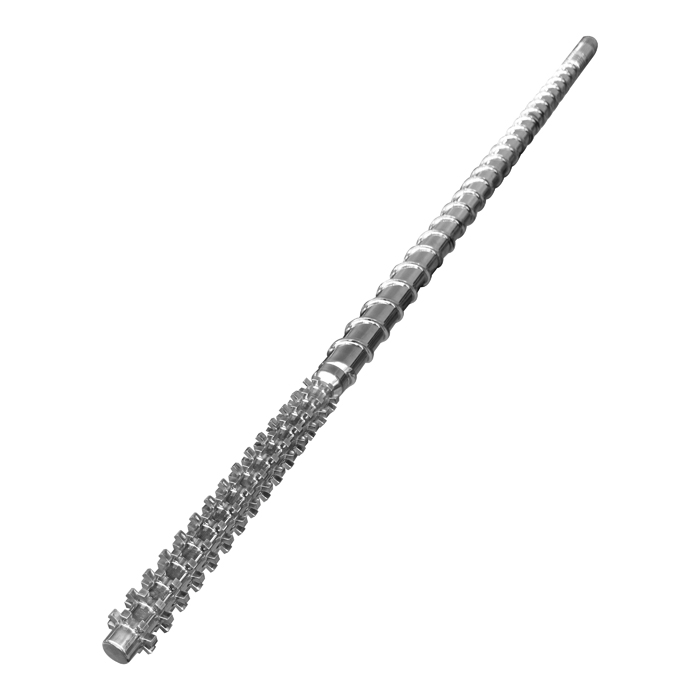
1. Identify the extrusion blow molding screw and barrel you are replacing
Identify the exact plasticizing assembly before comparing replacement extruder screws and barrels. Record the machine model, extruder or injection-unit designation, current part numbers and any previous conversion. On a multilayer line, also identify which material stream the component serves.
Confirm the process and the screw's actual duty
Extrusion blow molding forms a parison that is captured in a mold and inflated into a hollow part. Blown film forms a continuous film tube; injection blow molding uses an injection-molded preform. The component name should match the process and installed assembly. Use the EJS blow molding versus blown film guide for the initial distinction.
Within blow molding, confirm continuous-extrusion, accumulator-head or reciprocating arrangements from the actual OEM documentation. A cyclic molding operation does not by itself prove that the screw stops each cycle. Likewise, an injection molding screw and its front-end assembly should not be assumed interchangeable with an EBM set.
Resin, regrind and additives
Convey, melt, mix and deliver
Receive melt and form the parison
Identify the material stream on a coextrusion line
Specify whether the screw feeds the main resin, regrind layer or another material stream. Different layers can have different feed rates and material requirements. An inquiry that identifies only the complete machine leaves the replacement position ambiguous.
2. Extruder screw wear issues in blow molding: what should you check first?
Use production changes to trigger an investigation, then establish whether component wear is involved. Compare a repeatable material and product condition before attributing lower output, parison variation or black specks to the screw and barrel.
| Observation | Also investigate | Record before deciding |
|---|---|---|
| Lower output or more rpm needed | Material/feed changes, restrictions and temperature control | Timed total output, rpm, resin blend, pressure location and actual melt temperature |
| Parison sag or unstable drop | Melt condition, material behavior, drop time and machine sequence | Parison observations, material identity and time-related settings |
| Wall distribution changes | Head/tooling condition, temperature balance and parison control | Where the variation occurs and the corresponding process records |
| Black specks or streaking | Feed contamination, degraded deposits, head and heater condition | Material/changeover history, photographs and when the defect appears |
Formosa's Formolene polyethylene blow molding process guide lists multiple possible causes for parison and appearance problems. Its November 2008 edition is useful for understanding that diagnostic distinction; use current grade-specific and machine instructions for operating decisions.
Record measured melt temperature separately from barrel setpoints. Identify where pressure is measured, and keep melt pressure separate from blowing-air pressure. If physical inspection follows, pair the production record with screw and barrel measurements rather than treating the symptom table as a diagnosis.
3. Specify resin, regrind and feed conditions
"HDPE with regrind" leaves several inputs unresolved. Record the exact resin and the condition of the blend reaching the screw. A change in feed form or consistency may alter the job even when the polymer family stays the same.
| Input | What to state | Why the record matters |
|---|---|---|
| Resin | Supplier, grade and relevant material data | PE or PP alone does not identify the grade |
| Melt flow data | Value, unit, test temperature and load | Values measured under different conditions are not directly comparable |
| Regrind or PCR | Source, blend proportion and lot variation | Internal trim and an external recycled stream are different feed descriptions |
| Physical feed form | Pellets, granulate, flake, fines and bulk-density basis | Defines the feed condition to reproduce in the review |
| Additives | Colorant, filler and other formulation changes | Allows the proposed geometry and construction to be reviewed against the actual blend |
| Material stream | Layer or extruder position on the line | Prevents one layer's requirements from being applied to another unit |
Agree how the blend is measured and sampled. A quoted regrind percentage needs a defined mass basis and a description of the material itself. It is not a blanket approval for every container or application.
My recommendation is to resolve a changing feed condition before specifying a geometry change around it. Otherwise, the replacement may be judged against a different blend from the one used to define its task.
4. Calculate the melt demand the replacement must actually meet
Calculate the material passing through the screw, including the portion discharged as flash and tails. Finished-part mass, total processed mass and fresh-material consumption describe different flows.
Total melt per cycle = net part mass × parts per cycle + discharged flash and tail mass
Multiply kg/cycle by cycles/hour to calculate the cycle-average melt demand.
A worked mass-balance example
For this example, I assume two parts completed every 24 seconds, each weighing 120 g after trimming, plus 60 g of flash and tails per cycle. No other losses are included. These are hypothetical inputs for explaining the calculation.
| Quantity | Calculation | Result |
|---|---|---|
| Cycles per hour | 3,600 ÷ 24 | 150 cycles/h |
| Parts per hour | 150 × 2 | 300 parts/h |
| Net finished-part mass | 300 × 120 ÷ 1,000 | 36 kg/h |
| Flash and tails | 150 × 60 ÷ 1,000 | 9 kg/h |
| Total melt demand | 150 × (2 × 120 + 60) ÷ 1,000 | 45 kg/h |
Looking only at finished parts gives 36 kg/h. The screw's total duty in this example is 45 kg/h, including the 9 kg/h that becomes flash and tails. I would use the total when defining the plasticizing requirement.
Regrind circulation still uses plasticizing capacity
Now assume all of that clean trim is approved for reuse, the system is at steady state and there are no additional losses. Fresh-material input could then be 36 kg/h, with 9 kg/h circulating as regrind. The screw still processes 45 kg/h. Reuse reduces the fresh-material requirement but does not remove the recycled material's next pass through the screw.
Fresh material 36 kg/h
Returned trim 9 kg/h
Finished parts 36 kg/h
Flash and tails 9 kg/h
Return loop: 9 kg/h of trim goes back to the feed system.
I would then check feed form, actual plasticizing time, pressure and melt quality against that demand. On an accumulator or reciprocating system, use the real sequence to establish when and how melt is supplied. Parison ejection rate is not automatically the screw's cycle-average throughput.
Read rated output with its material conditions
Bekum's original Extrusion heads & Extruder brochure, PDF page 8, illustrates why a single kg/h value is incomplete. Its S60N model in the SxxN 24D table has separate output rows:
| OEM model | Material row | Listed output range |
|---|---|---|
| S60N, 24D | HDPE | 5 to 120 kg/h |
| Same model | HDPE / regrind, 70% / 30% | 5 to 110 kg/h |
| Same model | PP | 7 to 80 kg/h |
The brochure's footnotes qualify speed by material, the HDPE row by bulk density, the regrind row by bulk density and melt pressure, and PP by grade variation. These are Bekum specifications, not EJS ratings or compatibility approvals. Confirm the actual machine's documentation before applying them.
5. Check the extruder feed barrel, screw geometry and cooling connections
Define what the supplier means by "extruder feed barrel" on your machine. It may describe a feed-section component or be used more broadly for the barrel assembly. Match the name to the part number and drawing; a feed throat, feed bush and complete heated barrel are not interchangeable descriptions.
Identify smooth-bore and grooved-feed construction
Inspect the original feed arrangement and its mating screw geometry, cooling connections and component boundaries. Bekum's brochure separately describes a grooved-barrel 24D design and its HiPEx 36D technology. The example supports checking the complete configuration; it does not establish that every replacement should use either design.
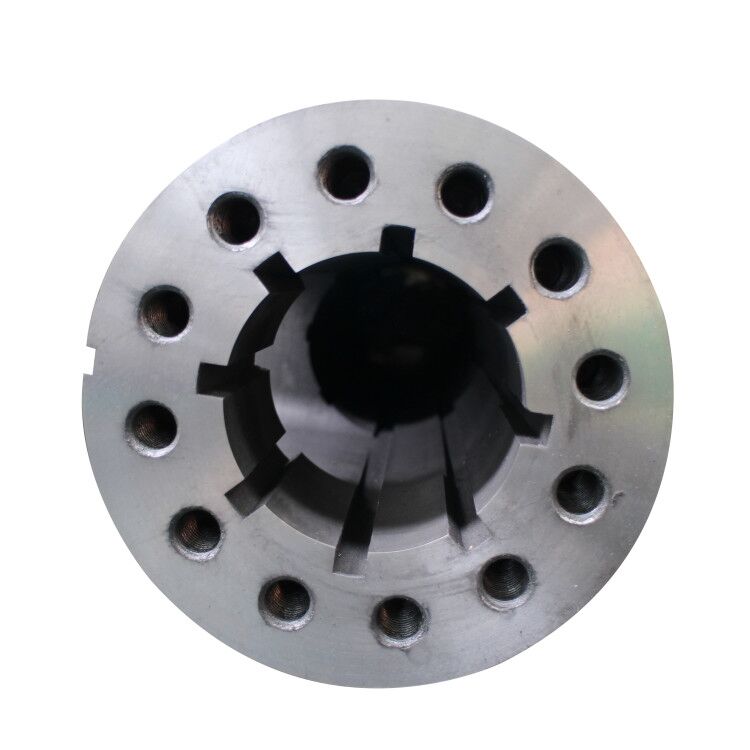
Record the working geometry, not just diameter
Specify working and overall lengths separately. Identify channel depths, pitch, compression or barrier features and mixing sections where applicable. L/D is useful context, but two extruder screws with the same diameter and L/D can still differ in geometry and connections.
Review melting and mixing requirements alongside melt temperature and drive limitations. Longer screws, stronger mixing and higher speed are choices with conditions, not universal upgrades. A like-for-like replacement should recover the approved geometry; a redesign needs a stated objective and review of the surrounding system.
6. Decide whether to replace the screw, barrel or matched set
Measure both components before choosing the replacement scope. Match screw outside-diameter and barrel inside-diameter readings at defined axial locations and directions, using specified measurement conditions. Local enlargement, ovality, scoring or damage can matter even when a single overall dimension looks acceptable.
Diametral clearance = barrel ID − screw OD
Radial clearance = diametral clearance ÷ 2
Use corresponding measurement locations and identify which definition the drawing or service limit uses.
For the complete measurement method and interpretation, see the EJS wear measurement and replacement guide. Do not turn a generic clearance ratio, elapsed service time or another machine's limit into this assembly's acceptance criterion.
| Proposed scope | Evidence needed | What still needs review |
|---|---|---|
| Replace the screw only | Remaining barrel dimensions and condition meet the agreed requirements | Matched clearances, feed section and interfaces |
| Replace the barrel only | Retained screw geometry, condition and connections remain suitable | Whether the assembled pair restores the required fit |
| Replace the matched set | Defined new-part drawings and full supply boundary | Reused feed, drive and adapter components |
| Evaluate rebuilding or relining | Case-specific assessment of the existing component | Restored geometry, construction, inspection and process requirements |
Identify every new, repaired and reused item on the order. A worn sample is evidence of current condition, not automatically a nominal manufacturing drawing. Rebuilding feasibility also needs a component-specific assessment rather than a promise based on the word "repairable."
7. Verify every mechanical and thermal interface before ordering
BEFORE ORDERING BY DIAMETER
If I received an inquiry saying that bottle weight was varying and the parison was sagging, with a request to replace the screw and barrel at the original diameter, I would first separate the production problem from the replacement specification. I would confirm the resin grade, regrind proportion and feed condition, then compare output, rpm, actual melt temperature and head pressure under the same conditions. Material, temperature control, the head and machine timing can all be involved; appearance alone cannot establish screw wear.
For component inspection, I would ask for screw OD and barrel ID measurements at corresponding locations, together with records of scoring, ovality and feed-section condition. If the machine uses grooved feeding, I would review the screw, feed section and cooling connections together.
Only then would I define whether the task restores the existing design or changes it. Worn dimensions should not become new-part nominal dimensions, and the same diameter does not establish matching interfaces. After drawing approval, component inspection and a material trial should have separate records for dimensions, installation and production results.
| Interface or feature | Record on the approved specification | Evidence to attach |
|---|---|---|
| Drive end and location | Splines or keys, coupling, rotation direction, locating shoulders and axial envelope | Machine interface drawing and labeled photographs |
| Screw and bore | Nominal geometry, working/overall lengths and matched bore definition | Controlled part drawings and inspection locations |
| Feed section | Feed opening, separate bushes or sleeves, mounting and internal features | Assembly drawing and identified mating components |
| Discharge end | Head-adapter connection, flange or thread, sealing and flow-path interface | Adapter/connection drawing and supply boundary |
| Thermal and sensing features | Heater zones, sensor-hole position/depth and cooling connections | Drawing, circuit identification and machine requirements |
Coupling · shoulders
Rotation · axial position
Internal features · mounting
Heaters · sensors · cooling
Adapter · flange or thread
Seal · flow-path interface
Use those same evidence fields in the clarification sheet: value and unit, drawing revision or measurement location, confirmed or unresolved status, and who will close the item. This makes missing information visible before it becomes a manufacturing assumption.
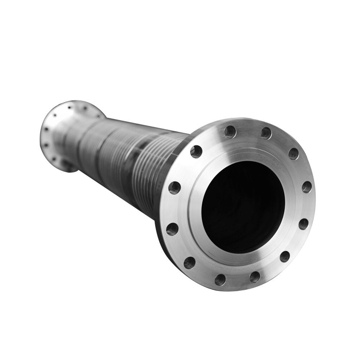
8. Separate component inspection from production validation
A dimensional inspection establishes whether a manufactured part meets its agreed specification. A material trial establishes what the installed configuration does under the recorded conditions. Plan both, with a clear division of responsibility.
Freeze the component definition before manufacture
Confirm the drawing revision, new/reused component list, specified material and treatment, inspection locations and document requirements. Ask for an actual specification rather than relying on a construction label such as "bimetallic." The general document checks are covered in the EJS screw barrel quality inspection guide.
| Stage | Evidence | Decision basis |
|---|---|---|
| Before shipment | Part identification, measured dimensions and specified material/treatment documents | Approved drawings and purchase specification |
| Installation review | Confirmed mating parts, connections and machine configuration | Actual machine and component requirements |
| Production trial | Resin/regrind record, settings, timed total output, melt condition and parison/product results | Agreed product and operating criteria, duration and sampling plan |
Define what counts as a successful trial
Use the agreed resin, blend, product, mold and operating sequence. Record where output is measured and what counts as an acceptable part. Weight, wall distribution, appearance and any application-specific tests should follow the actual product requirements.
A short peak-output demonstration is different from sustained acceptable production. Agree the test duration, sample quantities, pass/fail criteria and treatment of unresolved items before the trial. Keep component acceptance and process results linked to the same part identity without using one as a substitute for the other.
9. What to send EJS for an extrusion blow molding replacement review
Send a package that identifies the hardware, its duty and the change you want. EJS lists nitrided and bimetallic options for its extrusion blow molding screws and barrels; the construction should be reviewed against the actual material and agreed component specification.
- Machine and plasticizing-unit identification, layer/material-stream position and current part numbers.
- Available drawings, revisions, labeled photographs and measurements of the parts and mating connections.
- Resin grade, regrind/PCR source and proportion, additives and physical feed condition.
- Net part mass, discharged flash/tail mass, parts per cycle and the relevant time basis.
- Current process observations, wear measurements and the condition of retained components.
- The objective and supply boundary: restore the existing design, evaluate a change, and identify what is new or reused.
EJS's product page states that inspection reports and material certificates are provided. Define the required records on the order and connect them to the approved drawing and supplied part identities.
Prepare the replacement specification with EJS
Send the information you have and identify any unresolved dimensions or operating conditions. The review can then focus on the component and evidence required for your job.
sales@ejsscrewbarrel.com
+86-574-83065911
10. Frequently asked questions
Can I order a replacement by screw diameter alone?
No. Diameter does not establish working geometry, feed-section design, drive and locating features, head connection or thermal interfaces. Identify the installed assembly and supply a controlled drawing or sufficient verified information to develop one before manufacture.
Are injection molding screws and barrels interchangeable with an extrusion blow molding set?
Do not assume interchangeability. Injection molding and extrusion blow molding components must match their actual machine, motion, material duty and mating assemblies. Process names and nominal diameter alone cannot approve a replacement. The same caution applies when comparing blown film components with an EBM set.
Does a bottle-weight change prove that the screw and barrel are worn?
No. A weight change is a reason to investigate the complete relevant process. Record material and feed conditions, temperatures, pressure location, head/tooling condition and machine settings, then assess physical condition and dimensions where needed. The observation alone does not identify the failed component.
Should returned flash be included in required plasticizing output?
Yes, when it is fed through the screw again. Approved trim reuse changes fresh-material consumption, but recycled material still contributes to the screw's total throughput. Define the mass balance, reuse conditions and other losses so the same material is neither omitted nor counted twice in one pass.
Does switching to a bimetallic construction solve inconsistent feeding?
Not by itself. A construction change does not establish that feed form, blending, feed-section geometry, cooling or other operating conditions are suitable. Review the source of the inconsistency and the component's actual wear or corrosion requirements before specifying a change.
What can I provide if the original OEM drawing is missing?
Start with the machine and unit identification, part numbers, labeled photographs, measurements and mating-component information. Separate current worn measurements from proposed new-part dimensions. Resolve missing features into an agreed drawing and supply scope before production.