The word “parallel” describes the axes of the two screws. It does not tell you their rotation direction, element arrangement or whether the barrel is one piece or segmented.
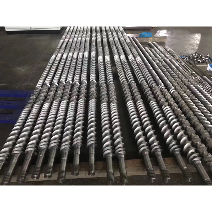
This distinction matters when a buyer needs replacement parts. “Parallel twin screw” narrows the machine family, but it is not a complete specification. Two systems with the same nominal screw diameter can differ in center distance, screw profile, rotation, working length, shaft connection, barrel ports and process layout.
What “parallel” means in the hardware
Look at the two shaft centerlines from the gearbox toward the die. In a parallel design, those centerlines remain the same distance apart. The working diameters also remain nominally constant along the process section. In a conical design, the screw axes and diameters change along the length.
The gearbox and barrel bore geometry establish this layout. A replacement part must follow the existing machine. Changing only the screws does not convert a conical machine to a parallel one, or the reverse.
Parallel geometry does not define rotation
A parallel twin screw extruder can use screws that turn in the same direction or in opposite directions. Those are different kinematic arrangements. They change how the flights meet, how material moves through the intermeshing region and how the screws must be handed and timed.
Current machine documentation gives examples of both. Thermo Fisher describes its Process 11 as a fully segmented, co-rotating parallel twin screw extruder. KraussMaffei lists modular co-rotating ZE systems and also supplies counter-rotating twin screw extruders in parallel and conical configurations. These examples show why “parallel” cannot be used as shorthand for “co-rotating.”
| Question | What it identifies | Why a replacement supplier needs it |
|---|---|---|
| Are the axes parallel or conical? | Machine geometry | It sets the basic screw and barrel layout. |
| Do the screws co-rotate or counter-rotate? | Rotation relationship | It affects screw hand, intermeshing geometry and timing. |
| Is the process section segmented or integral? | Construction style | It defines whether individual elements or sections can be specified. |
| What is the screw profile and sequence? | Process configuration | It determines conveying, mixing, kneading and pressure-building functions. |
For a deeper explanation of rotation, use the related co-rotating and counter-rotating guide after its final website URL has been confirmed.
Two common process-section construction styles
Segmented screw and barrel systems
Many parallel compounding extruders use removable screw elements on splined shafts and barrel housings assembled in sections. The elements can provide conveying, mixing, kneading and transition functions. Vents, liquid ports and side-feed openings can be assigned to selected barrel positions.
Thermo Fisher’s official process note shows segmented screws arranged into feed, melting, mixing, venting and extrusion zones. KraussMaffei likewise describes modular screws and housings for its ZE co-rotating extruders. These are manufacturer examples, not universal rules for every parallel machine.
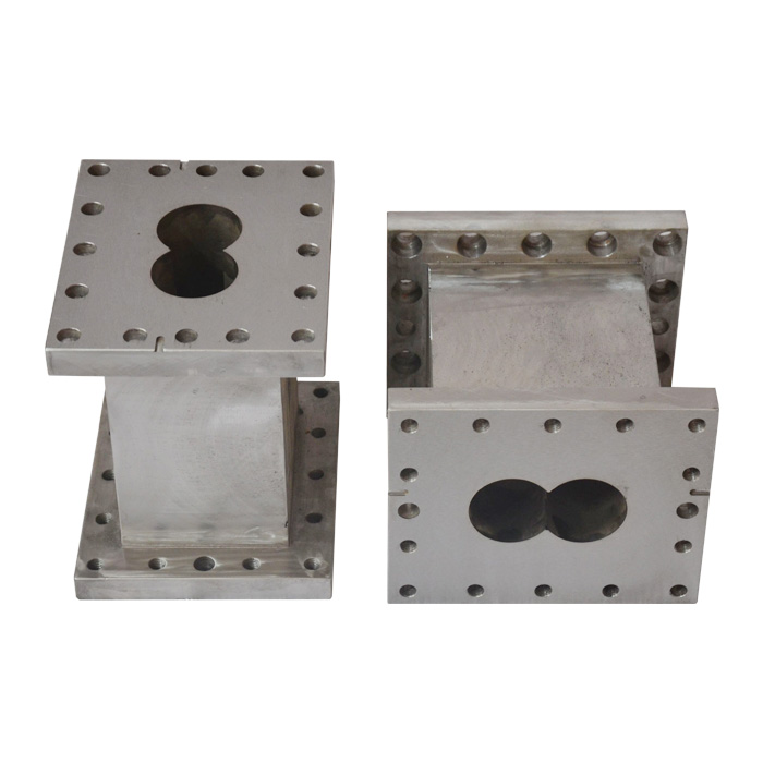
EJS currently lists screw elements, barrel sections and segment twin screw barrels. Its screw-element page asks buyers to provide a drawing with surface-treatment requirements or a sample for quotation.
Longer one-piece screws and barrels
Other parallel machines use long screw bodies and an integral or lined barrel rather than a process section assembled from many short elements. This arrangement appears in pipe, profile, sheet and other extrusion equipment. The replacement job then depends on the complete screw profile, barrel bore, working length, end connections and auxiliary openings.
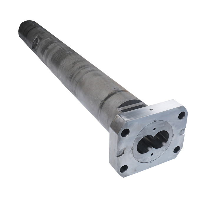
Do not infer construction style from the end product alone. Ask whether the machine uses removable elements and barrel blocks or full-length parts, then confirm it from the existing assembly, manual or drawing.
What belongs to the twin screw process section?
The word “screw barrel” is often used for the whole process section, but a modular parallel system contains several separately specified components:
- Screw shafts transmit torque from the drive to the mounted elements.
- Screw elements provide the local conveying, kneading, mixing or transition geometry.
- Barrel sections form the twin bore and may include feed, vent, side-feed, liquid-injection or closed positions.
- End connections and seals locate the process section relative to the gearbox and downstream equipment.
- Heating and cooling provisions belong to the barrel design and must match the machine installation.
In an integral design, several of these functions are built into longer components. The buyer still needs to record each interface. A barrel that fits the screw diameter but misses a flange, heater layout or centerline reference is not a usable replacement.
How to identify the installed system
Start with records before taking the machine apart. Photograph the machine nameplate, gearbox plate, process section and discharge end. Collect the operating manual, old purchase order, assembly drawing and any previous inspection report. Record all model suffixes rather than shortening the model to its first number.
- Confirm that the two axes remain parallel through the process section.
- Confirm rotation direction from the machine documentation and drive-end reference.
- Record whether the screws are intermeshing and whether the process section is modular or integral.
- Mark left and right screws as viewed from one stated end. Do not use “left” without defining the viewing direction.
- Number screw elements and barrel sections from a fixed datum before removal.
- Photograph ports, thermocouple holes, heaters, cooling connections, flanges and drive ends.
Specifications needed for a replacement
A machine model is useful, but it should be supported by dimensions and interface evidence. Machine builders may revise a process section without changing the main model name. Rebuilt gearboxes and earlier replacement parts add another source of variation.
| Specification group | Record this | Common source |
|---|---|---|
| Machine identity | Maker, full model, serial number, build year and gearbox identification | Nameplates, manual, purchase records |
| Basic geometry | Screw diameter, center distance, working length and overall length | Approved drawing and controlled measurement |
| Screw relationship | Co- or counter-rotation, viewing direction, screw hand and intermeshing profile | Manual, assembly record, marked removed pair |
| Drive interface | Shaft or spline profile, tooth count, major and minor dimensions, engagement length and end details | Drawing, unworn sample, inspection report |
| Process layout | Element sequence or full screw profile; barrel-section order and position | Assembly map and removal photographs |
| Barrel interfaces | Bore, flanges, bolt pattern, feed opening, vents, ports, heaters and cooling connections | Drawing and dimensional inspection |
| Service conditions | Polymer, fillers, corrosive additives, operating temperature and observed wear location | Recipe and maintenance records |
| Material request | Approved material, treatment and required supporting records | Original specification or application review |
If an original drawing is unavailable, send an unworn spare when possible. A worn sample can still help, but it should arrive with wear measurements, machine records and a clear statement that it is not the nominal master.
Prepare a useful parallel twin screw RFQ
Send enough information to identify both the geometry and the service condition. EJS can review the package and tell you which additional measurements are needed before a manufacturing drawing is approved.
- Machine and gearbox nameplates
- Original drawing or marked sample
- Screw diameter and center distance
- Rotation and viewing direction
- Left/right screw and element map
- Shaft or spline connection details
- Barrel-section position and ports
- Polymer, filler and additive details
- Current wear or failure photographs
- Requested inspection documents
Frequently asked questions
Does “parallel twin screw” mean co-rotating?
No. Parallel describes the screw-axis geometry. Parallel twin screw machines can be co-rotating or counter-rotating, so the rotation relationship must be specified separately.
Can a parallel screw pair replace a conical screw pair?
No. The gearbox shaft layout and barrel bore geometry are different. A replacement must follow the original machine configuration.
Are all parallel twin screw barrels segmented?
No. Modular screw elements and barrel sections are common in compounding equipment, while other parallel extrusion machines use longer one-piece screws and barrels.
Is screw diameter enough to order a replacement?
No. Center distance, working length, rotation, screw profile, drive connection and barrel interfaces can differ even when the nominal diameter is the same.
What should I do if I have no original drawing?
Send the complete machine and gearbox identification, assembly photographs, previous records and an unworn sample if available. If only a worn part is available, mark which dimensions may have changed in service.
Why must barrel sections be identified by position?
Sections can have different feed openings, vents, ports, heating or cooling connections and end interfaces. A correct bore alone does not make two sections interchangeable.
Checked sources
- EJS parallel twin screw barrel category, checked August 26, 2026.
- EJS twin parallel screw barrel product page, checked August 26, 2026.
- EJS screw element product page and EJS segment barrel product page, checked August 26, 2026.
- Thermo Fisher Scientific Process 11 product documentation, checked August 2026.
- Thermo Fisher Scientific, Relevant Process Parameters for Twin Screw Compounding, accessed August 2026.
- KraussMaffei ZE BluePower documentation and counter-rotating twin screw extruder documentation, checked August 2026.