Element wear, damaged shaft splines and rising torque can appear together, but they do not prove the same failure. A useful inspection traces each symptom to a location, measurement and operating condition.
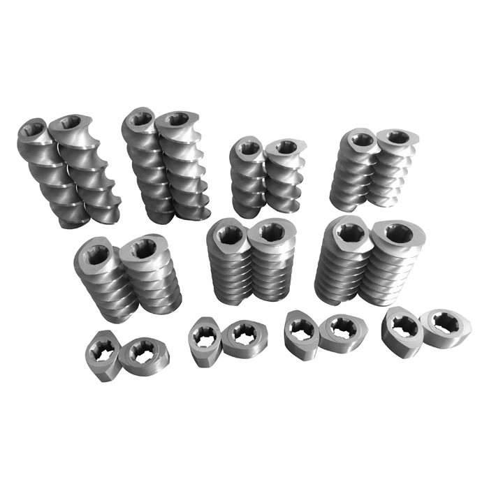
A modular twin screw process section contains more interfaces than a one-piece screw. An element can wear at its crest or flank. A barrel lobe can wear in one orientation. The connection between the shaft and element can lose fit. A high drive load can also come from the recipe, feed condition, temperature profile or screw arrangement.
That is why a parts list should follow the inspection, not replace it. The goal is to separate process evidence from dimensional evidence before deciding whether to replace elements, a barrel section, a shaft or a larger matched assembly.
Start with the evidence, not the suspected part
Write down when the problem began and what changed immediately before it. A new filler level, lower barrel temperature, altered feed rate, changed element sequence or downstream restriction can raise load without any new wear. A gradual change under the same operating conditions points more strongly toward wear or a developing mechanical problem, but it still needs measurement.
| Observed symptom | Check first | What the symptom does not prove |
|---|---|---|
| Drive torque or motor load rises | Recipe, feed rate, screw speed, barrel setpoints, melt pressure, screw configuration and gearbox alarms | It does not prove that the screw elements are worn. |
| Output or mixing quality changes | Feeder accuracy, raw material, vents, die restriction, element sequence and wear map | It does not identify one failed element from product quality alone. |
| Metallic noise or sudden vibration | Stop according to the machine maker's procedure, then inspect the process section, coupling, bearings and gearbox | It does not show whether contact started at the screw pair, barrel or drive. |
| Elements are difficult to remove | Residual material, shaft condition, element bore, axial clamping and approved removal procedure | It does not justify hammering, heating or forcing the assembly. |
| One zone shows heavy scoring | Matching screw elements, both barrel lobes, nearby ports, alignment and material history | It does not mean that the visible part is the only damaged component. |
Inspect screw element wear by position
EJS currently lists conveying elements, mixing elements, kneading blocks and several special profiles on its screw element product page. Those elements do different jobs and do not see identical stress. A loose pile of parts loses the relationship between profile, process zone and observed wear.
Preserve the sequence before cleaning
- Mark the drive end and discharge end on the removal record.
- Identify shaft A and shaft B using tags that survive cleaning.
- Number every element in axial order, including thin spacers and transition pieces.
- Photograph both assembled screws from the same reference end.
- Record where feed openings, side feeders, vents and pressure-building zones sit beside the element map.
Measure each suspect element at the same defined locations used on the drawing or on an unworn reference part. Record the instrument, measurement temperature and whether the value comes from a new drawing, a spare element or the used component. A photograph can document scoring or a chipped edge, but it cannot establish the remaining fit.
Coperion's current wear guidance treats protection by process zone. It identifies melting, abrasive mixing and pressure build-up as areas that can receive different wear protection. The specific zones vary by machine and application, so the inspection report should connect each measurement to the actual element sequence rather than assume one universal wear location.
Measure both lobes of every barrel section
A figure-eight bore is not one circular diameter. A useful report identifies the barrel section, axial measurement point, lobe and measurement orientation. Keep the same method for later inspections so the readings can be compared.
Coperion describes barrel-bore measurement as part of its current twin screw inspection service and uses the measurements to document equipment condition and recommend actions, including replacement of worn screw elements. The important part is the recorded measurement, not a visual judgment through the feed opening.
Position also matters when sourcing a replacement. EJS asks customers ordering a segment barrel to state whether it sits at the front, middle or tail because the connections differ. Add the section number, port layout, heater or cooling features, bolt pattern and adjoining faces to the drawing package.
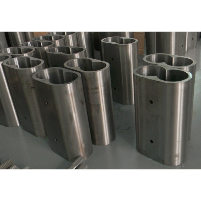
Do not average several bore readings into one number and discard the locations. Local wear can disappear in an average. Keep the raw values, drawing references and measurement orientation in the inspection record.
Check the shaft and element bore as one connection
The shaft carries torque from the gearbox into the screw elements. Coperion's current STS 75 Mc PLUS page makes that load path explicit: its screw-shaft materials are selected to transmit torque from the gearbox to the elements. The mating profile inside each element is part of the same connection.
After approved cleaning, inspect the shaft profile, element bore and drive-end coupling for damaged flanks, displaced material, corrosion products, cracks and uneven contact marks. Record where each mark appears. A new element on a damaged shaft may not restore the intended fit, while a sound shaft should not be condemned because one element is worn.
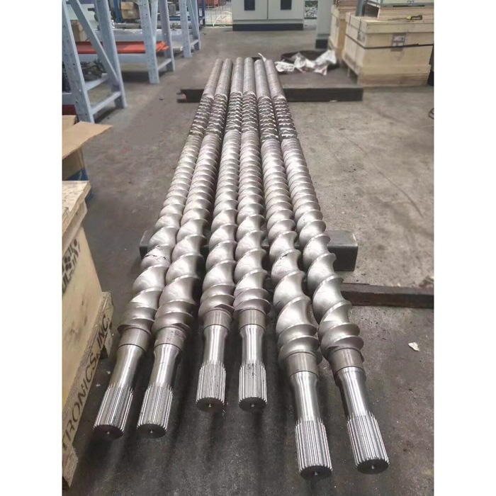
For a replacement RFQ, include the shaft drawing or a dimensioned inspection report. Useful fields include the profile type, tooth or lobe count where applicable, major and minor dimensions, engagement length, axial retention method, shaft-end connection and position of the damaged area. The machine maker's drawing and limits control acceptance.
Treat rising torque as a process signal first
Torque is useful when it is compared under controlled conditions. Compare the same formulation, throughput, screw speed, temperature profile, downstream restriction and screw configuration after the machine reaches a comparable steady state. If several variables changed, the trend cannot isolate hardware wear.
Thermo Fisher's twin screw process note shows why the context matters. It describes how throughput, screw speed and the arrangement of conveying and mixing elements affect residence time and melt temperature. A change in element sequence can therefore change the load even when every component is new.
A sudden torque spike with noise, vibration or pressure change calls for the machine maker's shutdown and inspection procedure. A slow increase under repeatable conditions belongs in the maintenance record with barrel-bore measurements, element dimensions and gearbox observations. Do not invent a universal alarm percentage or replacement threshold; use the limits for the exact extruder and drive.
Decide what to replace from the complete wear map
| Possible scope | Evidence needed before selection | What still needs checking |
|---|---|---|
| Selected screw elements | Localized out-of-limit element dimensions with a confirmed sequence | Shaft fit, mating elements and the barrel bore at the same zone |
| Elements and shaft | Documented damage or out-of-limit fit at both mating profiles | Drive coupling, axial retention and cause of the damage |
| Barrel section or liner | Position-specific bore measurements outside the machine maker's limit | Matching element wear, interfaces, ports and adjoining sections |
| Larger matched process-section set | Damage across several parts, unknown sequence history or contact between matched components | Gearbox alignment, timing, bearings and the original machine specification |
Modularity can reduce replacement scope, but only when the retained interfaces remain within the machine maker's limits. Replacing the most visibly worn piece while ignoring its mating surface may move the problem into the next production run.
Build an inspection and RFQ package
EJS's current screw element page asks customers to send drawings or samples, while its segment barrel page asks for the section position. Send the records below together so the supplier can trace every requested part to the machine and process position.
- Machine maker, full model, serial number and build year
- Operating hours since the last process-section inspection
- Recipe, fillers, feed rate, screw speed and temperature profile
- Torque, pressure and output records before and after the change
- Complete screw sequence for shaft A and shaft B
- Element numbers, dimensions and photographs with a scale
- Shaft and element-bore profile drawings
- Barrel-section map with front, middle or tail position
- Raw bore measurements by lobe, orientation and axial point
- Ports, heating, cooling, flange and bolt details
- Gearbox, bearing or coupling observations from qualified service staff
- Requested quantity and the parts you expect to retain
Frequently asked questions
Does high torque mean my twin screw elements are worn?
No. Torque also changes with formulation, feed rate, screw speed, temperature, downstream restriction and screw configuration. Compare repeatable operating conditions, then use dimensional inspection to confirm wear.
Can I replace only the visibly worn screw elements?
Only after checking the shaft fit, mating elements and barrel bore in the same process zone against the machine maker's limits. The most visible damage may not show the full replacement scope.
What should I record before removing screw elements?
Mark the drive and discharge ends, label both shafts, number every element in order, photograph the assembled screws, and map the sequence to feed ports, vents and other barrel positions.
Why does the barrel section position matter?
Sections can differ in ports, heating or cooling features, bolt patterns and adjoining connections. EJS asks buyers to identify whether a segment is at the front, middle or tail when ordering.
Can a photograph confirm shaft spline wear?
A photograph can document visible damage, but it cannot confirm the remaining fit or dimensions. Send the shaft drawing and measured profile data for an engineering review.
Should barrel bore readings be averaged?
Keep the individual readings by section, lobe, orientation and axial position. An overall average can hide localized wear that affects the replacement decision.
Sources checked for this guide
Product wording and available parts can change. These pages were checked on August 25, 2026.
- EJS screw element
- EJS segment barrel
- EJS parallel twin screw barrel
- Coperion twin screw inspection and barrel-bore measurement
- Coperion wear protection for screw elements and barrels
- Coperion STS screw shaft and torque transmission
- Thermo Fisher Scientific twin screw process parameters
- Coperion ZSK maintenance access and safety interlock