The practical difference is not which term sounds better. It is whether a replacement screw, shaft, element or barrel section matches the machine already on your floor.
Co-rotating
Both screws turn in the same direction when viewed from the same end.
Counter-rotating
The two screws turn in opposite directions when viewed from the same end.
The arrows above are only a definition. They are not enough for manufacturing. A supplier still needs to know which end you used as the viewing reference, which screw is left or right, and how each screw connects to its drive shaft.
For an existing extruder, the useful question is not, “Should I buy co-rotating or counter-rotating?” The useful question is, “Which architecture does this machine use, and what evidence proves it?” Changing rotation is a machine redesign issue. It is not a normal like-for-like screw and barrel replacement.
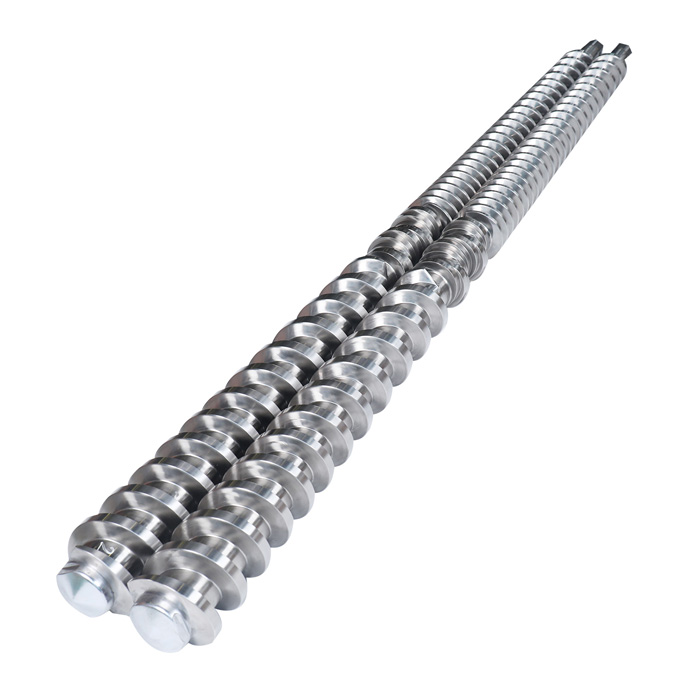
What changes between the two systems?
Rotation affects the gearbox outputs, screw geometry, shaft connections and the relationship between the two working profiles. It also changes which replacement details matter most. The table below is written for maintenance and purchasing teams, not for choosing a complete new extrusion process.
| Check | Co-rotating system | Counter-rotating system |
|---|---|---|
| Rotation | Both screws turn in the same direction. | The screws turn in opposite directions. |
| Current machine examples | EJS describes its pelletizer twin screw barrel for a high-speed co-rotating compounding extruder. KraussMaffei's ZE BluePower is a current co-rotating compounding platform. | KraussMaffei currently groups both conical and parallel extruders in its counter-rotating range for PVC processing. |
| Common replacement form | Shafts, screw elements, kneading blocks and barrel sections may be ordered as position-specific parts on modular lines. | A matched screw pair and matching barrel are common replacement units, especially on conical PVC lines. Parallel counter-rotating systems also exist. |
| Easy mistake | Sending the element diameter but losing the original element sequence, shaft spline or barrel-section position. | Sending only a model or diameter code without the left/right screw hand, drive connection, center distance and barrel interfaces. |
| Best first evidence | Machine nameplate, gearbox or shaft drawing, marked element sequence and dimensions of the removed parts. | Machine nameplate, original screw and barrel drawings, marked left/right parts and drive-end dimensions. |
How do you identify the rotation on an existing extruder?
Start with records, then confirm them against the machine. Old purchase descriptions can be incomplete, and a model name may have variants. Use more than one of the following checks before requesting a manufacturing drawing.
- Photograph the machine nameplate. Include the manufacturer, full model, serial number and build year if present.
- Find the gearbox or shaft drawing. It should identify the two outputs, center distance, rotation and drive connection.
- Mark the viewing end. Write “viewed from drive end” or “viewed from discharge end” on the photo. Never send clockwise arrows without this reference.
- Mark left and right before removal. Use durable tags that stay with each screw and shaft. Add an arrow for material flow.
- Photograph the screw engagement. Take an overall pair photo, then close views of the drive end, discharge end and any transition zones.
- Compare the records with the parts. If the drawing and removed parts disagree, stop and resolve the difference before production.
If the screws cannot be removed yet, send the gearbox drawing, existing maintenance photographs and the machine maker's parts record. Do not open guards or approach rotating parts for the sake of an RFQ photo. Follow the machine maker's lockout and inspection procedure.
Parallel does not automatically mean co-rotating
“Parallel” and “conical” describe the geometry of the screw axes and diameters. “Co-rotating” and “counter-rotating” describe motion. They are separate fields in a replacement specification.
This distinction prevents a common shortcut. A buyer sees two parallel bores and labels the machine co-rotating. That can be wrong. KraussMaffei's current counter-rotating portfolio includes both parallel and conical series, while EJS's current pelletizer twin screw barrel is described for a co-rotating extruder.
Use four separate descriptions in the RFQ: parallel or conical, co-rotating or counter-rotating, intermeshing arrangement as shown on the drawing, and the left/right drive details. If any field is unknown, label it unknown and send photographs rather than guessing.

What does each replacement type require?
For modular co-rotating parts
Do not remove all screw elements and place them in one unmarked box. Record the order from the drive end to the discharge end, keep the two shafts separate, and photograph every transition. Measure the shaft, spline or key connection as well as the element outside diameter and bore.
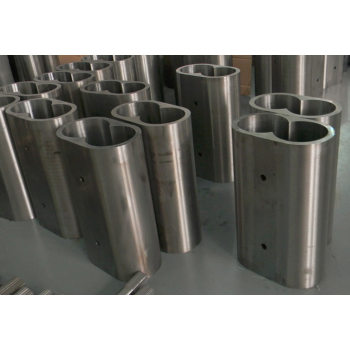
Barrel sections also need position data. EJS's current segment barrel page asks buyers to state whether a section sits at the front, middle or tail because the connections can differ. Add the section number, port position, heater or cooling features, bolt pattern and adjoining faces.
For matched counter-rotating parts
Keep the screws as a labeled pair. Record the smaller and larger diameters for a conical set, or the working diameter for a parallel set. Add overall length, working length, center distance, screw hand, drive-end spline or key, thrust faces and tip geometry. For the barrel, show every flange, mounting face, feed opening, vent, sensor hole, heating zone and cooling passage.
Do not assume that two machines sharing a short size code use interchangeable parts. The same nominal diameter can sit on a different gearbox, spline, length or barrel connection. An approved manufacturing drawing should close those gaps before steel is cut.
Six ordering mistakes that delay a replacement
- Ordering by diameter alone. Diameter does not define length, center distance, drive connection or working profile.
- Sending rotation arrows without a viewing end. Clockwise from the drive end becomes counterclockwise from the opposite end.
- Mixing left and right parts after removal. A matched pair needs permanent identification through inspection, packing and drawing approval.
- Losing the screw element sequence. A bag of loose elements does not show the original process arrangement.
- Ignoring barrel-section position. Ports, connections and adjoining faces may change along the line.
- Copying a worn dimension as the original size. State whether a measurement comes from a drawing, an unworn reference area or a worn working surface.
Label first, photograph before disassembly, measure from stated reference points, and separate confirmed dimensions from wear measurements. The replacement supplier can then trace each number to a drawing, location or physical surface.
Choose material after the architecture is confirmed
Material and wear protection matter, but they cannot rescue a part with the wrong rotation, spline or geometry. First confirm the machine interface. Then describe the resin, fillers, reinforcement, corrosive additives, operating temperature, output target and observed wear location.
EJS currently lists nitrided, bimetallic and lined options across its parallel twin screw barrel, plastic compounding twin screw barrel and segment barrel pages. The published list is a starting point, not an automatic selection. The final recommendation should match the confirmed formulation, part geometry and wear pattern.
Abrasive wear near a feed or kneading zone is a different problem from corrosion along a heated barrel. Send close photographs and measurements from the damaged zone. If the formulation has changed since the original part was supplied, say so in the RFQ.
Send a replacement RFQ that can be checked
A complete package reduces back-and-forth and makes drawing approval more meaningful. Send confirmed documents where possible, then identify every value taken from a used part.
- Machine maker, model, serial number and build year
- Co-rotating or counter-rotating, with viewing end marked
- Parallel or conical geometry
- Original drawings or a dimensioned sample
- Left and right screw labels
- Overall length, working length and center distance
- Spline, key, shaft and drive-end dimensions
- Element sequence or complete screw profile
- Barrel-section position and all port locations
- Resin, filler, reinforcement and corrosive additives
- Wear photographs and measured clearances
- Quantity and required delivery destination
Frequently asked questions
Can I replace a counter-rotating screw pair with a co-rotating pair?
Not as a normal replacement. Rotation is tied to the gearbox outputs, shaft connections, screw geometry and matching barrel. A change would require an engineering review of the machine, not just a new screw pair.
Are all parallel twin screw extruders co-rotating?
No. Parallel describes geometry, not rotation. Both co-rotating and counter-rotating parallel systems exist, so confirm direction from the machine documents and physical parts.
How should I photograph twin screw rotation?
Mark the viewing end, label the left and right screws, add the material-flow direction, and show both drive connections in the same set of photographs. Do not send clockwise arrows without the viewing reference.
What information is needed for replacement screw elements?
Send the machine model, shaft drawing, element outside diameter and bore, spline details, complete element sequence, position marks, material formulation and wear photographs.
Can EJS quote from a machine model only?
A model is a useful starting point, but it may not prove every interface. Drawings, marked photographs and dimensions from the removed parts are needed to confirm the manufacturing specification.
Should I choose the material before sending the drawings?
No. First confirm fit, rotation and geometry. Then select the material and treatment from the resin, fillers, corrosive additives, operating conditions and actual wear pattern.
Sources checked for this guide
Product availability and wording can change. These pages were checked on August 22, 2026.