A custom part should not enter production on the strength of a machine model and a few photographs. The buyer and supplier need one approved definition of the geometry, material, interfaces and inspection evidence.
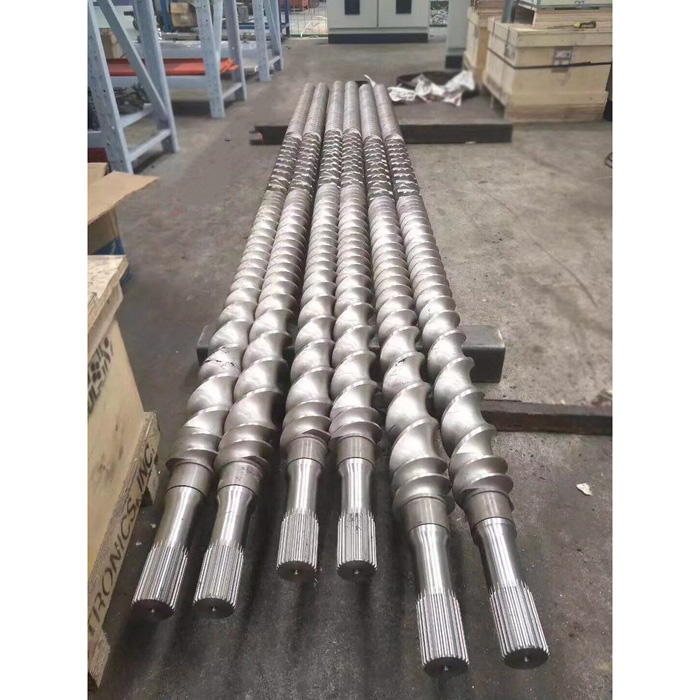
Custom twin screw work has two kinds of risk. One is obvious: a flange, bore or shaft connection does not fit. The other appears after installation: the pair assembles, but the screw relationship, element sequence, material selection or local clearance does not match the service.
The purchasing process should catch both. This guide shows the decisions a buyer can control without pretending that every manufacturer uses the same machines or shop sequence.
Choose the evidence route before requesting a drawing
The best starting evidence is the latest approved OEM or machine-builder drawing for the installed configuration. If that is unavailable, use several independent records rather than one worn part.
| Starting evidence | What it can establish | What still needs checking |
|---|---|---|
| Current approved drawing | Nominal dimensions, datums, interfaces and specified material | Revision, machine serial applicability and any field modifications |
| Unworn spare part | Physical geometry and assembly interfaces | Material, treatment, original tolerances and whether the spare is correct |
| Used screw or barrel | Overall layout, ports, connections and remaining geometry | Original crest, bore, flank, spline and sealing dimensions |
| Machine model and records | Equipment family and prior purchase history | Exact revision, serial-specific changes and installed modifications |
| Measurement report plus photographs | Selected dimensions tied to visible features | Datum scheme, tool capability, inaccessible features and wear correction |
Keep a provenance note beside every important value: drawing revision, measured new spare, measured used part, machine manual or agreed engineering value. If two sources conflict, stop and resolve the conflict before issuing a production drawing.
Freeze the interfaces that make the part fit
A twin screw system is a connected assembly. The screw pair, barrel bore, gearbox output and downstream adapter have to share the same references. Record the complete machine and gearbox identification, including serial numbers and model suffixes, before measuring the process section.
Screw and shaft interfaces
- Parallel or conical geometry, plus screw outside diameter and center distance.
- Co-rotating or counter-rotating relationship, with the viewing direction stated.
- Left and right identification, screw hand, tip-end details and overall length.
- Shaft or spline form, tooth count, major and minor dimensions, engagement length and end retention.
- For modular screws, the element sequence, element widths, orientation and shaft position.
Barrel and machine interfaces
- Twin-bore form, length, end faces, locating diameters and flange bolt pattern.
- Feed throat, vents, side-feed openings, liquid ports and sensor holes.
- Heater arrangement, cooling passages and external clearances.
- For segmented barrels, each section's position from a fixed gearbox-side datum.
- Connection to the gearbox housing and the downstream adapter or die.
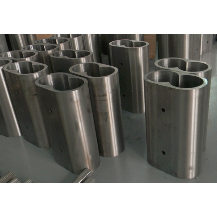
EJS's current segment barrel page specifically asks buyers to identify whether a section belongs at the front, middle or tail because its connections differ. For a more complex line, a numbered barrel map is safer than those three broad labels.
Define the service before selecting material
Geometry answers “will it fit?” The application determines what the working surfaces must withstand. Provide the actual polymer family, filler and reinforcement, filler loading, corrosive or reactive additives, color-change demands, normal temperatures, screw speed and the location of previous wear.
A generic request for “the hardest material” is incomplete. Wear can vary along the process section. A feed zone, kneading zone, vent area and pressure-building section do not see the same combination of solids, temperature and stress. Coperion's wear guidance likewise treats protection as application- and zone-dependent.
Ask the supplier to state the proposed base material, working-surface treatment and the reason for the choice. If the application has food-contact, pharmaceutical or other regulated requirements, state them at inquiry stage and list the documents you need. Do not assume that a material name by itself proves regulatory compliance.
Approve a manufacturing drawing, not an email summary
The manufacturing drawing should turn the evidence package into one controlled definition. It needs a drawing number and revision. Each critical dimension should refer to an explicit datum. Notes should identify the material, treatment, surface requirement, paired-part identification and inspection requirement.
Before approval, check these items line by line:
- Machine and part identification
- Drawing revision and units
- Reference end and datum scheme
- Parallel or conical geometry
- Center distance and bore layout
- Left/right and viewing direction
- Rotation relationship
- Shaft or spline interface
- Flanges and locating surfaces
- Ports and section positions
- Material and surface treatment
- Critical inspection characteristics
- Part marking and pair marking
- Required records and packing method
Do not approve the drawing because the overall shape looks familiar. Compare it with the machine interface and your measurement report. Mark every unresolved dimension rather than assuming the supplier will infer it during machining.
Set production checkpoints around risk
The buyer does not need to prescribe every factory operation. The useful control points are the stages after which a mistake becomes expensive to correct.
| Checkpoint | Buyer should confirm | Typical evidence |
|---|---|---|
| Technical review | Inputs are complete and contradictions are resolved | Review notes and approved drawing revision |
| Material release | Specified material and traceability requirement are understood | Material record identified to the order |
| Pre-treatment geometry | Critical stock and interfaces remain available for final processing | In-process dimensional record where agreed |
| Post-treatment condition | Specified treatment and any required test locations are recorded | Treatment record and agreed test results |
| Final inspection | Critical dimensions, pair relationship and part identity match the approved drawing | Signed inspection report tied to part and revision |
| Packing release | Surfaces, loose elements and matched parts are protected and identifiable | Packing photographs and packing list |
An official Coperion brochure provides one useful industry example of risk-based inspection. It describes checks for screw-element timing and crest width, barrel and gearbox geometry, assembly alignment, material composition and hardness. That is evidence of Coperion's process, not proof that EJS uses the same equipment or inspection sequence. Use it to frame questions, then agree on the EJS inspection plan for the specific order.
Specify the records you expect before shipment
A statement that a part “passed inspection” has little value unless it identifies the part, drawing revision, characteristic, result and acceptance requirement. The report should use the same datums and terminology as the approved drawing.
Depending on the part and contract, a practical record package may include:
- Part number, drawing revision, order number and unique part or pair identification.
- Material certificate or other agreed material record linked to the supplied component.
- Results for the dimensions marked critical on the drawing.
- Agreed treatment, hardness or surface-condition records, with method and location where applicable.
- Element-sequence or barrel-section map for modular assemblies.
- Final photographs of drive ends, bore ends, flanges, ports, markings and packing.
The current EJS twin parallel screw barrel page states that EJS provides an inspection report and material certificate for supplied screw barrels. Buyers should still place the exact required records and acceptance points on the order because a general certificate does not replace project-specific inspection criteria.
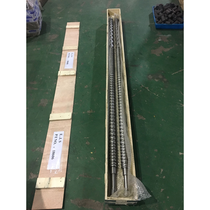
Review the documents before shipment, not after the crate reaches your plant. If a critical value is missing, it is easier to recheck while the part and inspection equipment are still at the supplier.
Build a quotation package that can become a production record
Use the same organized package for quotation, drawing review and final acceptance. This reduces the chance that a dimension supplied in an early email disappears from the approved specification.
- Machine, gearbox and serial details
- Original drawing and revision
- Marked sample status: new or worn
- Dimension report with stated datums
- Left/right and rotation reference
- Element or barrel-section map
- Polymer, filler and additive details
- Operating and wear information
- Material and treatment request
- Required inspection documents
- Quantity and part marking
- Packing and receiving requirements
Frequently asked questions
Can a custom twin screw barrel be made without an original drawing?
It may be possible, but the project needs other controlled evidence such as machine identification, an unworn spare, measured samples, assembly photographs and service records. The supplier and buyer should resolve worn or uncertain dimensions before approving the manufacturing drawing.
Can I send a worn screw or barrel as the sample?
Yes, but identify it as worn and provide any baseline or wear measurements you have. Dimensions taken from a used crest, bore, flank or spline should not automatically be treated as nominal new-part dimensions.
What must be approved before production starts?
Approve the drawing revision, datums, critical dimensions, paired-part relationship, material, treatment, inspection points, required records and part marking. Commercial approval alone is not a technical release.
Why does the supplier need polymer and filler information?
The service conditions help the supplier review material and working-surface choices. Wear and corrosion exposure can vary by resin, filler, additives and position along the process section.
What should a final inspection report identify?
It should identify the part, order, drawing revision, inspected characteristic, result and acceptance requirement. Critical results should use the same datums and units as the approved drawing.
Does a material certificate prove that the finished part fits?
No. A material record addresses material identity or properties within its stated scope. Fit and assembly still depend on dimensional inspection against the approved drawing.
Checked sources
- EJS twin parallel screw barrel product page, checked August 26, 2026.
- EJS screw element product page and EJS segment barrel product page, checked August 26, 2026.
- EJS parallel twin screw barrel category, checked August 26, 2026.
- Coperion CTE twin screw extruder brochure, accessed August 2026. Used only as an external manufacturer example of inspection subjects.
- Coperion wear and corrosion resistant solutions, checked August 2026.