Choose a sheet extrusion screw and barrel by defining the resin, feed form and sheet quality targets, then matching the melting, mixing, venting and wear requirements to the installed machine. Confirm the drawings before ordering and judge the replacement by stable, accepted sheet production.
A request for a replacement often starts with screw diameter and required kilograms per hour. Those two numbers leave the difficult questions open. Is the line losing melting capacity, struggling to feed regrind, or producing a persistent thickness difference across the sheet? Each calls for a different investigation.
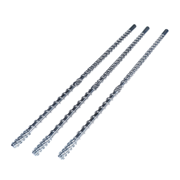
EJS supplies sheet extrusion screws and barrels for single- and twin-screw systems. The useful starting point for a specification is the installed plasticizing unit and its actual duty. A more elaborate screw profile earns its place when it addresses a documented processing limit.
Define the Sheet, Resin and Production Duty
Write the replacement objective in production terms. A clear display sheet, a filled industrial board and a thermoforming sheet can require different surface quality, thickness control and downstream behavior. Specify the sheet width and thickness range, the acceptable defects, and the operating rates that matter commercially.
Record the resin supplier and grade, masterbatch, fillers and additives. For regrind, include its source, proportion, particle form and consistency. A change from free-flowing pellets to irregular flakes changes the feeding question even when the polymer name stays the same.
| Input | What to record | Decision it supports |
|---|---|---|
| Sheet requirement | Width, thickness range, surface criteria and later forming or fabrication | Define accepted production and inspection points |
| Feedstock | Grade, pellet or flake form, regrind source, blend ratio and fillers | Separate feeding, melting and wear demands |
| Installed unit | Machine model, screw arrangement, venting, filtration and melt pump if fitted | Identify the component and its pressure-building duty |
| Current limitation | Measured defect, output trend, melt condition and adjustment history | Choose between restoring geometry and changing the design |
For multilayer sheet, identify the affected extruder and layer. Record each layer's material and flow requirement. Total line output does not describe the duty of a small skin-layer screw, and the overall sheet thickness does not establish whether the individual layer distribution is acceptable.
Match Screw Design to the Material and Feeding Conditions
PP and PE sheet
For a polyolefin line, establish whether the immediate constraint is solids feeding, melting, blend uniformity or pressure delivery. A feed change and a melting limitation can both reduce output, but adding mixing length does little to resolve inconsistent material entry.
LyondellBasell's polyolefin sheet extrusion guide describes a typical PE/PP screw with a 3:1 compression ratio and an L/D of at least 24:1. These are contextual design examples in a PE/PP manual, rather than a universal replacement specification. Existing geometry, formulation and the required operating range still need review.
PET and copolyester sheet
Identify the precise material and how moisture is controlled before deciding whether to change the venting arrangement. Obtain the grade's processing instructions and confirm the installed drying or devolatilization system. A vent opening by itself does not establish moisture-removal capability.
For example, battenfeld-cincinnati describes its STARextruder for PET processing with a high-vacuum planetary roller system. That is a specific system architecture. A conventional replacement screw should not be assumed to reproduce its treatment of incoming material.
Other resins and filled formulations
For PS, ABS, PMMA, PC or PVC sheet, request the actual grade or formulation and original machine details. Review appearance, thermal history, additives and feed preparation together. The term “plastic extruder screw” covers too many duties to establish a suitable geometry without these inputs.
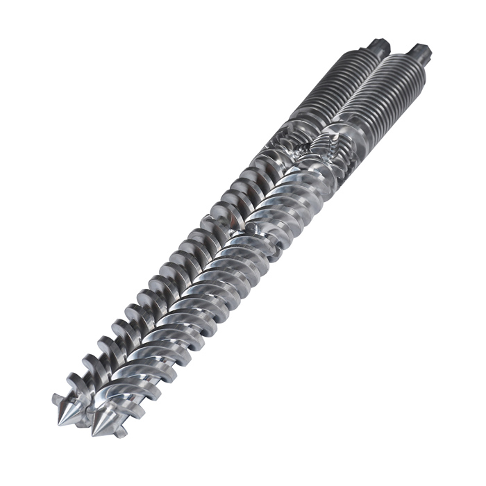
For a twin-screw line, confirm conical or parallel geometry and rotation arrangement from the machine documentation. Sheet production alone does not identify the architecture. Keep a photograph of the drive end and the original paired-part identification with the inquiry.
Screw Design for Sheet Extrusion: Compression Ratio, Mixing and Venting
Review geometry in the order material passes through it. The feed section must accept and convey the supplied feedstock. The melting section must prepare it within the available drive and thermal limits. Mixing and pressure delivery must then meet the requirements of the downstream equipment.
Read the geometric definitions correctly
L/D uses the working length and reference screw diameter specified on the drawing. For a conventional constant-pitch screw, feed-channel depth divided by metering-channel depth can approximate geometric compression ratio when channel widths and other assumptions are comparable. Changing pitch, flight arrangement or channel geometry requires a volume-based comparison.
One ratio does not define the complete screw
3.0 mm
1.0 mm
3.0 ÷ 1.0 = 3.0
Illustrative constant-pitch geometry with comparable channel widths. The result does not specify melting length, barrier clearance or mixing intensity.
A barrier screw adds a separation function during melting. A mixing section serves a different task. Specify whether the required improvement is temperature distribution, color distribution or breakup of agglomerates, then evaluate the added shear and pressure demand. “More mixing” is an incomplete design instruction.
When comparing resin flow data, retain the test method, temperature and load. ISO 1133-1:2022 defines MFR and MVR measurements under specified conditions. A melt-flow test temperature is not a barrel-temperature recipe, and its result alone cannot select the screw profile.
The same discipline applies to temperature control. Record barrel setpoints separately from measured melt temperature and sensor location. For vented screws, the pressure and filling conditions around the vent must suit the process. Adding a port to an existing barrel is not a complete devolatilization design.
Diagnose Sheet Defects Before Changing the Screw
Start a replacement review with the last stable production condition. Compare resin grade, regrind proportion, drying records, screen condition, line speed and recent adjustments before attributing the problem to the screw. Then examine the production trends and physical condition of the parts.
Give every thickness measurement both a cross-web position and a time. A repeatable thin lane at one width position creates a different investigation from a thickness change affecting much of the width as production progresses. These patterns organize the checks; neither pattern proves a single cause.
| Observation | Useful evidence | Next check |
|---|---|---|
| Thickness changes over time | Time-aligned pressure, feed rate, screw speed, line speed and thickness | Look for a shared disturbance, allowing for material travel time |
| Persistent cross-web difference | Repeated width profiles, die settings and roll-condition records | Check flow distribution, gap and cooling before specifying a new screw |
| Visible specks or streaks | Defect samples, material history, filtration and cleaning records | Distinguish unmelt, contamination, deposits and poor distribution |
| Lower output at familiar settings | Actual material rate, screen pressure trend, feed condition and wear map | Separate feed restriction, pressure demand and component deterioration |
LyondellBasell's sheet guide treats the die's flow distribution, polishing-roll condition and thickness gauging as distinct parts of the process. This supports a practical boundary for a screw purchase. Improved plasticizing cannot be accepted as a complete remedy until the downstream contribution has also been checked.
Account for the distance from the extrusion measurement point to the sheet gauge. Comparing a pressure change with a thickness reading taken at exactly the same clock time may pair different material. Use line speed and the material path to estimate the delay, then check whether the events still correspond.
Screw and Barrel Wear: What Should You Replace?
Keep three questions separate. What material has been lost? What caused that loss? What component specification is needed for the next production duty? A hard surface cannot compensate for incorrect alignment, and a new screw cannot restore an enlarged barrel bore.
For filled sheet, include the filler identity, concentration and contamination history in the review. Specify the screw's working-surface protection and the barrel's working layer separately. Ask for the material, coverage, inspection method and required geometry of each component.
The EJS sheet-extrusion product page lists nitrided and bimetallic treatment options. Select the actual combination against the formulation and damage evidence. A treatment name or hardness figure alone does not establish a service-life multiplier.
Measure the screw flight diameter and barrel bore at corresponding axial positions and record the inspection conditions. Distinguish localized wear, ovality and scoring. Use the original drawing, new-part inspection record and applicable service limits to judge the measurements. The screw and barrel wear guide covers the broader measurement and replacement process.
Replacing one component can be reasonable when its mating part remains suitable. Document the resulting clearance and surface compatibility. If the old geometry performed well until progressive wear, restoring it may be the appropriate objective. A changed formulation or a new rate target requires a separate design review.
Extruder Screw Replacement for Sheet Lines: Drawings and Machine Fit
A usable drawing package connects the working geometry to the installed interfaces. Keep original design dimensions separate from measurements of a worn sample. Reverse engineering the old part without identifying wear can reproduce the loss of material.
| Area | Record and verify |
|---|---|
| Working geometry | Diameter, working length, channel progression, mixing features and vent positions |
| Drive and location | Spline or key details, locating faces, axial dimensions and assembly direction |
| Barrel interfaces | Feed opening, flange pattern, adapter connection, sensor holes and heater/cooling interfaces |
| Operating limits | Approved speed, drive load, pressure and temperature limits for the installed equipment |
| Document control | Drawing revision, paired-part identity, inspection locations and acceptance responsibility |
For an extruder feed barrel or a separate feed section, verify the opening and cooling connections against the actual machine. Feeding geometry is part of the installed system. The twin-screw feed barrel guide addresses that component when it is the part being investigated.
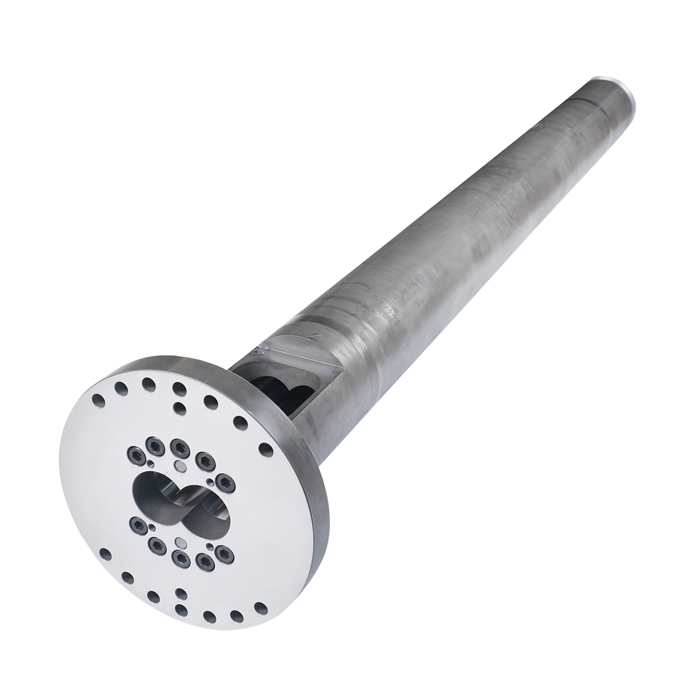
State whether the order restores the existing design or changes the processing duty. Identify each proposed geometry change and the result it is intended to improve. That record makes the later trial meaningful and helps prevent a mechanical fit from being mistaken for process acceptance.
Validate the Replacement with a Controlled Sheet Trial
Agree on acceptance before installation. Use the specified resin and blend, defined sheet dimensions, documented filtration and a representative operating range. Record actual melt temperature, pressure at identified locations, screw speed, drive load, line speed, thickness profiles and the defect count over a stated sample area.
Define accepted output after the agreed trim and quality rejection. If energy is compared, state which equipment is metered and divide by accepted kilograms over the same interval. Changing from an extruder-only measurement to a whole-line measurement invalidates a direct comparison.
Average thickness can conceal an unacceptable profile
Consider an illustrative solid sheet of constant density and width. If half its width is 0.90 mm thick and half is 1.10 mm, its width-average thickness is 1.00 mm. It has the same average mass per area as a uniform 1.00 mm sheet under those assumptions, but its local thickness differs by ±10%. A weight or average-thickness check therefore cannot replace a cross-web profile.
Wear measurements and replacement economics
For mineral-filled PP sheet extrusion, specify screw-flight protection and barrel-liner metallurgy separately, using the complete formulation and measured wear pattern. Surface hardness alone cannot establish service life. In a dimensional example, an 80.10 mm barrel bore paired with a 79.90 mm screw flight gives 0.20 mm diametral clearance, equivalent to 0.10 mm nominal radial clearance when concentric. These dimensions illustrate the calculation; acceptance limits must come from the approved drawing.
A nitrided assembly that wears prematurely in the actual formulation warrants investigation of both abrasive damage and screw-to-barrel contact before selecting an upgrade. Wear in the melting section can impair melt quality before output falls substantially, while gradual increases in screw speed can conceal the deterioration, as explained by Jim Frankland in Plastics Technology.
Evaluate replacement economics against cumulative accepted sheet production. In an illustrative comparison, an assembly costing 30% more to purchase and install must produce more than 1.30 times the accepted tonnage before replacement to reduce component cost per accepted tonne. If production records establish a 1.60-times increase, that cost falls by 18.75%, calculated as 1 − 1.30/1.60. This excludes energy, downtime and financing. A service-hour multiplier is equivalent only when average accepted output per operating hour remains unchanged.
Keep the commissioning result and later wear review as separate records. The first shows whether the replacement meets the operating task. The later review establishes whether the chosen working materials retain that performance over production.
Frequently Asked Questions
Can one screw process PP, PS and PET sheet?
Some systems can process more than one resin, but suitability depends on the complete screw geometry, feed preparation, venting and operating range. Check each grade and sheet requirement. Sharing a screw diameter does not establish interchangeable processing conditions.
Does PET sheet extrusion always require a vented screw?
No single vent arrangement applies to every PET sheet line. Confirm the grade, incoming material and the system used to control moisture and volatiles. A replacement must match the validated drying or devolatilization route of the installed line.
Should the screw and barrel be replaced together?
Measure both before deciding. Replacing one can be appropriate when the mating part remains within the approved dimensional and surface requirements. Check the resulting clearance and the cause of the original damage before accepting the combination.
Can replacing an extruder screw correct sheet thickness variation?
It can help when confirmed screw deterioration or unsuitable plasticizing contributes to the variation. Feed changes, filtration, die flow distribution, roll condition and line-speed control also need investigation. Use synchronized process readings and thickness profiles to establish the cause.
What information is needed for a sheet extrusion screw barrel quotation?
Provide the machine model, controlled drawings or dimensioned samples, resin and formulation, regrind conditions, sheet dimensions, current operating data and replacement objective. Include wear measurements, interface photographs and the proposed acceptance criteria when available.
Prepare a specification for your sheet line
EJS lists inspection reports and material certificates with its supplied screw barrels. Define the drawing revision, materials and inspection requirements in the order, then retain the records for the production trial and subsequent wear checks.
Send your machine details, drawings, formulation and sheet quality targets to sales@ejsscrewbarrel.com, or use the EJS contact page to discuss a sheet extrusion screw and barrel replacement.