Keep the existing blown film extruder screw and barrel if the new resin blend feeds steadily and produces film within specification at the required output. If performance falls, check what changed in the feed, screen pack, and cooling before changing the screw design. Use matched measurements of the screw flights and barrel bore to decide whether wear protection belongs in the replacement specification.
The first question in a replacement review is whether the current screw has lost performance on a recipe it used to run or whether a new recipe has exposed a limit the screw always had. The first points toward inspection. The second calls for a process comparison, with a separate record for each extruder on a coextrusion line.
Can You Keep the Same Screw After a Resin Change?
Start with the resin grade and the way it reaches the screw. Record the LDPE, LLDPE, or HDPE grade, the blend proportions by weight, the masterbatch, and the source and form of any recycled material. Ground edge trim, repelletized trim, and post-consumer pellets can feed and filter differently at the same nominal percentage. A material change can affect the bubble through melt behavior as well as through fluctuations in the amount entering the screw.
Compare melt mass-flow rate (MFR) or melt volume-flow rate (MVR) only when the test conditions match. Record the test temperature and load alongside the result. Similar MFR values are a useful screening observation, but blends can still behave differently in the melt channel and in the film bubble. For a three-layer film, record which extruder receives the changed blend and its contribution to total output. A steady total kg/h can hide a shift in the layer ratio. ISO 1133-1:2022, standard method for MFR and MVR.
Decide whether to keep, test, or redesign
- Keep the current screw when the new blend meets output, pressure, melt temperature, and film quality targets after the process settles.
- Run a matched comparison when the line ran the reference blend well and the problem appeared after a change in material, feed form, or filter setup.
- Review the screw profile when repeat runs show a melting or mixing limitation at the required rate and checks of feeding, filtration, cooling, and wear support that diagnosis.
How Do You Separate Feed Problems, Melt Defects, and Wear?
Bring the line to a stable condition on a known blend and record feed rate, screw speed, output, actual melt temperature, pressure, and film quality over the same interval. Then repeat the comparison with the changed blend or component. Use the same screen construction and record the differential pressure across it when instruments are available. A single pressure reading upstream of the screen records upstream pressure. It cannot isolate the pressure drop across the screen.
| Observed change | Check first | What it tells you |
|---|---|---|
| Feed or output fluctuates after adding loose regrind | Check feeder delivery over a timed interval, hopper bridging, bulk density, and consistency of the blend entering the feed opening. | Variable delivery can change output and layer ratio while screw speed stays steady. |
| Gels or specks rise as screen pressure drop climbs | Log the resin lot, screen age, and defect appearance. Compare equivalent screen conditions and inspect retained material under the plant’s procedure. | Filtration load is a separate lead. Classify defects before specifying a mixer or different screw profile. |
| Film thickness varies but extruder output holds steady | Check whether thickness bands stay in the same position around the bubble or vary over time. Compare die and air-ring settings, cooling, and haul-off behavior. | A repeating pattern in the same position points to checks around the die and cooling ring. Time-based changes should be compared with output and line-speed trends. |
| Output per revolution falls gradually on a known recipe | Compare feed, actual melt temperature, and screen condition with the original baseline. Map barrel bore and screw flight diameters at corresponding axial locations. | Paired measurements can show where clearance increased and whether the screw, the barrel, or both contributed. |
Calculate specific output as (kg/h × 1,000) ÷ (rpm × 60) to get grams per screw revolution. Use the output of the extruder being evaluated and compare it at the same operating point. In a metered-feed setup, check the feeder setpoint and actual delivery before interpreting a change in this ratio. LyondellBasell troubleshooting guide for blown film.
What Can a Recycled HDPE Trial Tell You About Gels?
Researchers at RWTH Aachen University compared six batches of pelletized post-consumer HDPE from the same recycling stream. Their monolayer blown-film setup used a 45 mm extruder with a 24:1 L/D, a blow-up ratio of 2.4, and an output of 10 kg/h. Impurities or gels disrupted the film bubble in the recycled batches. Material from the same waste stream and recycler that had undergone an extra filtration step ran successfully under the same blown-film settings. The team quantified gels separately on a cast-film line with optical inspection. Fischer et al., Polymers, 2025.
For a production line, use that result to decide what to isolate first. If bubble breaks or gels track a material lot, run a known reference lot with a comparable screen pack before ordering a new screw. If defects persist on the reference material, document their appearance and when they occur, including after idle periods or changeovers. A separate study of PE films identifies several possible sources of gel-like defects, including degraded polymer, unmelted material, and contamination. These require different corrective actions. Spalding et al., original research on gels in polyethylene film.
When Is an Alloy-Protected Screw and Barrel Worth the Cost?
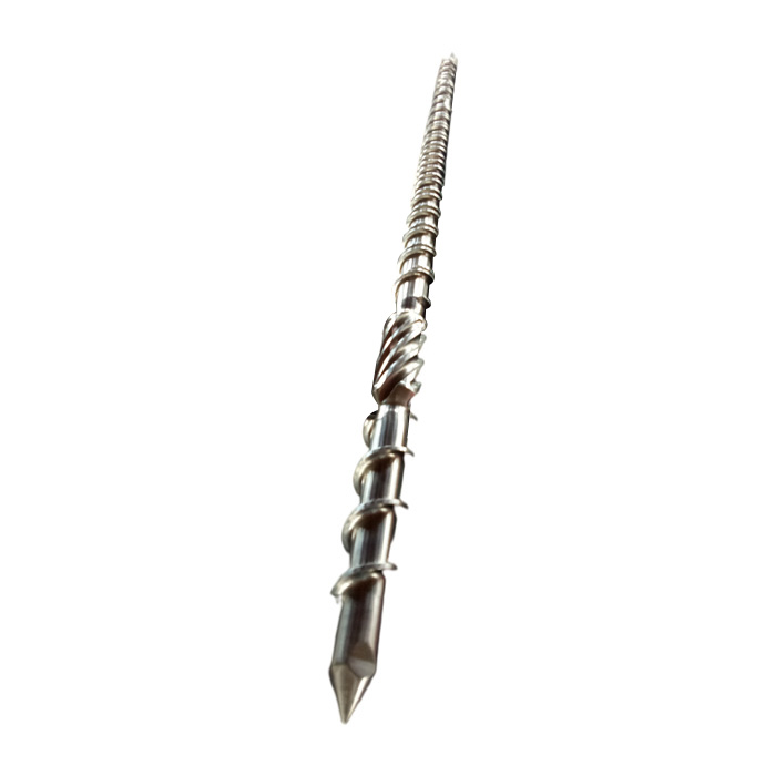
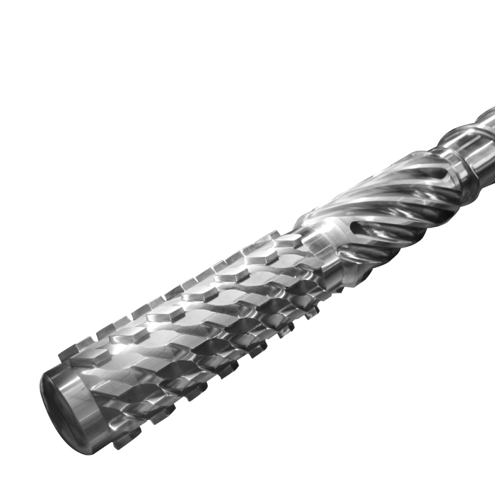
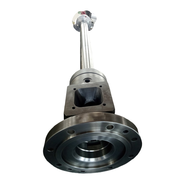
Choose the profile and the working surfaces separately. A barrier section separates solids from melt during melting. A mixing section can improve melt uniformity, with a possible cost in pressure or melt temperature that needs to be checked at the target rate. When inspection instead shows progressive wear, specify protection for the screw flights and barrel bore as a matched pair. EJS lists nitrided and alloy-coated options for its blown film screw and barrel assemblies. Ask the supplier to identify which working surfaces are protected and how the finished dimensions will be verified.
Calculate diametral clearance from matched measurements
For a PE line running abrasive regrind, measure bore ID and screw flight OD from the same axial datum and at a comparable measurement temperature. In this illustrative 90 mm assembly, the bore opens up while the flight diameter decreases. The two changes add together in the clearance calculation. A larger gap can increase melt leakage across the flights and reduce pumping efficiency under comparable conditions. Set the replacement criterion against the approved drawing and process performance. Marschik et al., flight-clearance leakage models.
One axial station, two sets of measurements
90.10 mm bore ID − 89.90 mm flight OD
0.20 mm diametral clearance
90.18 mm bore ID − 89.76 mm flight OD
0.42 mm diametral clearance
Compare replacement cost per tonne of accepted film
Use installed replacement cost divided by the tonnes of film that meet specification before the same replacement criterion is reached. In an illustrative comparison, a 35% higher installed cost requires 1.35 times the baseline accepted tonnage to break even. If the upgraded pair reaches 1.80 times the baseline accepted tonnage, its installed replacement cost per accepted tonne is 25% lower (1 − 1.35 ÷ 1.80). This tonnage ratio also represents the ratio of operating hours if the average rate of accepted production is the same. Use your maintenance records and accepted tonnage to evaluate the offer. Add any downtime or scrap costs that are outside the installed replacement price as separate lines in the comparison.
What Should You Verify Before Ordering and Accepting a Replacement?
Send the original machine drawing and a current wear map together. A removed screw can help identify the drive and locating features. Use the approved design dimensions for the replacement so wear on the old screw does not become part of the new drawing.
| Stage | Record or agree |
|---|---|
| Before quoting | Machine make and model, screw OD, working length, drive and locating details, barrel bore, feed opening location, discharge flange, and drawing revision. For a multilayer line, identify the extruder and layer. |
| Before manufacture | Resin grade and regrind range, target kg/h, problem to correct, protected surfaces, and dimensional inspection points with common datums. |
| At receiving inspection | Match the parts and inspection records to the approved revision. Check the specified interface dimensions and pair clearances at the agreed stations. |
| During the production trial | Define a stable run window and agree the acceptance limits for output, melt pressure and temperature, film thickness profile, and gel count. For gels, specify the detection size and inspected area. Retain a film sample and the matching machine settings. |
Send EJS your drawing and trial target. EJS manufactures blown film screws and barrels to customer drawings and lists dimensional inspection reports and material certificates with supplied parts. Email sales@ejsscrewbarrel.com or use the EJS contact page. Include the blend, extruder position, and the change you want to verify in production.
Frequently Asked Questions
Does adding regrind always require a different blown film screw?
Keep the existing screw if the regrind blend feeds consistently and meets output and film quality targets. If performance changes, compare feed delivery and screen-pack behavior with a known blend before deciding whether the screw profile needs to change.
Can a mixing section remove gels from polyethylene film?
A mixing section can help with poor melt uniformity when the defect responds to additional mixing. Contaminants and some crosslinked or degraded particles need a different response, such as a material investigation, filtration review, or a check for stagnant material. Identify the defect before specifying a mixer.
Can you replace the blown film screw and keep the existing barrel?
Yes, if the barrel bore and interfaces meet the approved limits for the replacement. Check the bore at several axial positions and compare it with the proposed screw flight diameter. A new screw in an enlarged or oval bore can leave excessive clearance.
How do you compare two screws if the line runs them at different speeds?
First compare them on the same blend and at a shared operating point, using output per revolution, melt temperature, pressure, and film quality. Then compare the highest stable output each can deliver while meeting the same film specification and machine limits.