Specify a cable extrusion screw and barrel from the exact compound, the layer being produced and the installed processing route. Match melting, mixing, thermal control and working-surface protection to that duty. Confirm the interfaces from drawings, then validate accepted cable production at the required line speed.
A PVC sheath, a crosslinkable insulation and a semiconductive screen can run at similar material rates while placing different demands on the plasticizing unit. Buying by diameter or polymer family alone leaves out the conditions that determine whether the replacement will work.
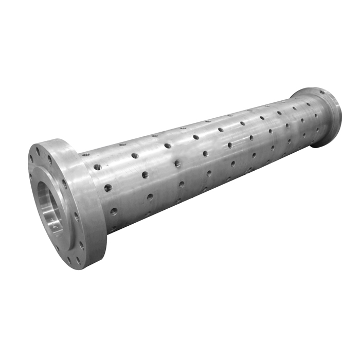
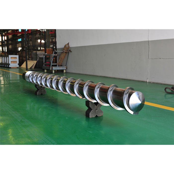
EJS produces wire and cable extrusion screws and barrels for applications including building wire, automotive, power and communication cable. A useful inquiry connects the actual formulation and layer to the original machine, the problem being addressed and a measurable acceptance plan.
Identify the Compound, Cable Layer and Processing Stage
Begin with what enters the screw and what must leave it. Producing a compound from polymers, fillers and additives is a different task from applying a ready-made compound to a conductor or cable core. Some installations combine stages, so confirm the actual route rather than assigning a process from the machine name.
Single-screw and twin-screw equipment
A single screw extrusion machine applying precompounded material needs to melt, homogenize and deliver that material within its processing window. A twin-screw extruder used for compounding may also need to meter powders, incorporate additives and carry out a different mixing or reaction task. Those requirements cannot be transferred unchanged to a cable-covering screw.
For a replacement, record the installed screw arrangement, rotation, feed system and downstream equipment. The existence of a twin-screw process for a compound does not establish that your cable line needs one. An architecture change also involves the drive, barrel and feeding system.
Identify whether the part serves insulation, bedding, sheath, conductor screen or insulation screen. On a multilayer line, record each extruder and its layer separately. Total cable weight and total line output do not describe the duty of an individual plasticizing unit.
Match the Screw to PVC, PE, XLPE and HFFR Compounds
Use the supplier, grade and complete formulation as the material identity. Include pigment or masterbatch, filler information, storage conditions and any crosslinking components introduced on the line. The following comparison defines the questions to resolve before specifying geometry or metallurgy.
| Material or layer | Review first | Specification consequence |
|---|---|---|
| PVC insulation or sheath | Exact plasticized compound, fillers, thermal history and feed form | Review melting, deposits, temperature control and observed surface damage |
| PE insulation or sheath | Grade, additives, layer dimensions and required cleanliness | Match melting and delivery stability to the operating range |
| Crosslinkable PE | Peroxide, silane or other defined processing route and component additions | Use grade-specific thermal, moisture and residence-time controls |
| HFFR / LSHF compound | Filler system, rheology, grade instructions and actual melt temperature | Balance homogenization with mechanical heat input and wear protection |
| Semiconductive screen | Ready-made compound, contamination control and bonding or stripping requirements | Preserve the supplier's material quality through controlled handling and extrusion |
For a PVC cable extruder machine, establish whether the feed is already compounded. A design brief for plasticized cable pellets should not be copied from a rigid-PVC dry-blend pipe process. Likewise, “XLPE” alone does not identify where crosslinking chemistry is introduced or how the material should be handled.
Ready-made semiconductive material also needs a precise identity. Borealis describes Borlink LE0511 as a silane-crosslinkable compound for a strippable insulation shield. Its data sheet emphasizes clean handling, preferably in closed systems. Treat this as a specific screen-material example, rather than a specification for every carbon-black-filled layer.
For rubber cable compounds, confirm the appropriate rubber-processing unit and cure system separately. The EJS rubber screw barrel range provides the relevant product starting point.
Screw Geometry for Cable Extrusion: Compression Ratio, Mixing and Heat Control
Specify the function of a proposed design change before choosing its shape. The feed section must accept the supplied material. Melting must be completed within the available drive and thermal limits. The remaining flow path must provide the required homogeneity and pressure delivery.
Read compression ratio in its geometric context
For a conventional constant-pitch screw with comparable channel widths, feed-channel depth divided by metering-channel depth can approximate geometric compression ratio. Changing pitch or channel arrangement requires a volume-based comparison. The number alone does not describe transition length, local shear or the material's time-temperature history.
A meaningful extrusion screw compression ratio discussion therefore includes the complete working profile. Higher compression is not an automatic route to better cable quality. Compare its purpose with the actual material and operating rate.
Define the mixing task
Distinguish distributing a color masterbatch through a ready-made compound from dispersing raw filler during compound manufacture. Adding a more restrictive mixer can change pressure demand and mechanical heating. State the defect or uniformity target it must improve, and the melt-temperature limit within which it must do so.
Alphagary's MEGOLON thermoplastic LSHF extrusion guidelines recommend low-compression, low-shear screw geometry for optimum output. That material-specific advice is a useful check against prescribing aggressive mixing for every highly filled cable compound.
Review barrier and conventional screw functions against the melting task. Also record the expected output range. Working length affects the available processing space, but L/D alone cannot establish residence time or guarantee scorch resistance.
Control Melt Temperature, Moisture and Scorch Risk
Record barrel setpoints separately from actual melt temperature, together with the sensor location and measurement method. A steady controller display does not establish the temperature history experienced by material throughout the flow path.
For MEGOLON thermoplastic LSHF compounds, Alphagary gives a preferred melt-temperature range of 165–175°C and presents its zone profile as a starting point requiring adjustment. These figures belong to that guide. Obtain the instructions for the grade in use before defining trial limits.
Higher screw speed can add mechanical heat. However, a high drive load does not justify a universal instruction to lower every temperature setting. Investigate incomplete plasticizing, restrictive tooling, feeding and actual melt condition together. Stay within the approved equipment and material limits while changing one documented variable at a time.
Drying instructions can differ between systems
The Visico LE4423/LE4437 data sheet identifies a silane-crosslinkable base-resin and catalyst-masterbatch system. It specifically advises against predrying LE4437 because of the drying agent in that product, and warns that humid exposure can cause scorch during extrusion. This is why a generic drying recipe cannot replace the compound supplier's instructions.
The contrast extends to thermal conditions. The Borlink LE0511 screen-compound sheet specifies an approximate extrusion melt range of 115–125°C and warns about poor mixing at lower temperatures and pre-cure or scorch at higher temperatures. Its conditions are for that particular grade and layer, not for all XLPE insulation or semiconductive materials.
For a new replacement design, review startup, interruption and restart conditions as well as steady running. A satisfactory result during a short continuous trial does not establish that the system tolerates every planned production pause.
Select Screw and Barrel Materials from the Actual Failure Mode
Separate geometry recovery from material selection. First establish where the screw or bore has lost material and whether the damage is abrasive, corrosive or associated with contact. Then determine the protection needed for the next production duty.
For filled compounds, record filler identity, loading and contamination history when available. A polished surface, pitting and deep scoring are different observations. Replacing a damaged part without checking its mating component and the reason for contact can leave the cause unresolved.
The EJS cable product page lists nitrided and bimetallic treatment options. A purchase specification should identify the screw's working-surface material and coverage separately from the barrel's working layer. Include the dimensional and surface inspections required after manufacture.
Measure screw-flight diameter and barrel bore at corresponding axial locations under the defined inspection conditions. Compare them with controlled drawings and a new-part baseline. Use the wear measurement and replacement guide for the broader measurement method.
Replacing one part may be appropriate when its mating part remains suitable and the resulting combination meets the agreed requirements. If both have deteriorated, changing only the screw may leave excessive clearance. A hardness value or alloy name alone cannot establish either the remaining fit or a service-life multiplier.
Diagnose Cable Defects Before Ordering Replacement Parts
Start the review with the last stable production condition. Compare compound batches, storage and handling, additions, line speed, tooling and adjustment history. Then align pressure, melt-temperature and drive-load records with the affected cable section.
External diameter, minimum insulation thickness and eccentricity answer different questions. For an ideal circular core and circular outer boundary, moving the core off center can leave outside diameter and total insulation area unchanged while reducing the thinnest wall. Checking only diameter or material weight can miss that local reduction.

| Observation | Evidence to collect | Question to resolve |
|---|---|---|
| Rough surface or bubbles | Grade instructions, material handling, actual melt temperature and defect samples | Is moisture, overheating, contamination or another material issue involved? |
| Diameter changes along the run | Polymer delivery, line speed, core dimensions and pressure trends | Which change corresponds to the affected cable length? |
| One side is consistently thin | Cross-sections, core position, centering and tooling condition | Is the problem distribution around the core rather than total material delivery? |
| Gels or dark specks | Material samples, thermal and interruption history, cleaning and flow-path inspection | Is there pre-cure, degraded residue or foreign material? |
| Output deteriorates over time | Same-material baseline, feeding and filtration checks, screw and bore measurements | Does measured component change explain the performance loss? |
Allow for travel time between the process measurement and the inspection point. A pressure event and a downstream dimensional reading taken at the same clock time may refer to different material. Inspecting the relevant reel length makes a stronger comparison than relying on a shift-average value.
Calculate Layer Output and Confirm Replacement Interfaces
Calculate the material rate for the layer supplied by each extruder. Use that layer's polymer mass per meter, excluding copper, aluminum and other layers. With line speed in meters per minute and layer mass in kilograms per meter, the required rate in kilograms per hour is their product multiplied by 60.
Illustrative sheath-material rate
0.080 kg/m
60 m/min
0.080 × 60 × 60 = 288 kg/h
The assumed rate excludes conductor mass and startup waste. It establishes a material-delivery requirement, not a screw diameter or a guaranteed accepted-output rate.
At startup or during a change, material consumption and accepted cable length need separate records. Define the required operating range, including the lower rates used for smaller products. A nominal maximum output alone does not establish stable performance across that range.
| Item | Record and verify |
|---|---|
| Processing duty | Compound grade, layer, material rate, line-speed range and present limitation |
| Working geometry | Screw diameter, working length, channel progression and functional sections |
| Mechanical fit | Drive spline or key, locating faces, axial dimensions, flange and head connection |
| Thermal interfaces | Feed-section cooling, heaters, sensor locations and any internal temperature-control connections |
| Acceptance records | Drawing revision, material specification, inspection locations and agreed trial conditions |
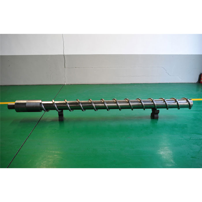
Keep worn-sample measurements separate from original design dimensions. For a redesign, identify each proposed change and the processing result it is intended to improve. This prevents a mechanically interchangeable part from being accepted without checking its production performance.
Validate the Screw on the Actual Cable Line
Agree on the compound, layer, tooling, line-speed range and acceptance criteria before the trial. Record actual melt temperature, pressure at identified locations, screw speed, drive load, polymer consumption and accepted cable length. Include dimensional measurements and the electrical or material tests required by the applicable cable specification.
IEC 60811-201, including its 2017 and 2023 amendments, describes insulation-thickness measurement methods. Use the relevant cable product specification to establish the acceptance requirements. A measurement method by itself does not certify the cable, and insulation and sheath requirements should be identified separately.
What a historical scale-up trial teaches
A 1999 Danish Environmental Protection Agency project report documents HFFR processing tests on a 63 mm extruder and a subsequent attempt to scale the screw design to a 150 mm cable extruder. The larger trial developed excessive compound temperature and did not reproduce the earlier success. This is a specific historical study, but its practical lesson remains useful. A screw proposal needs validation with the actual material, machine and downstream flow path.
HFFR processing and replacement economics
For the MEGOLON material family discussed above, low-shear processing and the published melt-temperature range provide a starting point for the review. In the 288 kg/h sheath example, verify that the line delivers that material rate without exceeding the grade's processing limits or losing accepted cable quality.
If inspection confirms abrasive flight and bore wear, evaluate screw hardfacing and a wear-resistant barrel liner separately, while retaining the geometry needed to control melt temperature. Increasing screw speed to compensate for deteriorating output can leave the original wear mechanism unresolved.
For an illustrative economic comparison, an upgraded assembly costing 40% more to purchase and install must deliver more than 1.40 times the accepted cable length before replacement to reduce component cost per accepted kilometer. If production records demonstrate 1.75 times the accepted length for the same cable specification, that cost is 20% lower, calculated as 1 − 1.40/1.75. Converting this result into an operating-hour life multiplier additionally requires unchanged average accepted output per hour. This component-cost comparison excludes energy, downtime and financing.
Keep initial process acceptance separate from the later wear review. The first establishes whether the installed replacement meets the production task. Subsequent measurements and accepted-length records establish whether its working materials retain that performance.
Frequently Asked Questions
Can the same screw process PVC, PE and HFFR?
It may be possible within a defined operating range, but suitability must be checked for each compound and cable layer. Compare feed preparation, melting, mixing, actual melt temperature and working-surface requirements. The same machine diameter does not establish a common processing window.
Does HFFR always need a twin-screw extruder?
No. Manufacturing an HFFR compound and applying a ready-made compound to a cable are different tasks. Confirm the material supplied, the processing route and the installed machine. Screw selection should address that task rather than follow a blanket rule based on the HFFR label.
Does a longer screw prevent XLPE scorch?
No. Scorch control depends on the specific crosslinkable system, its thermal history, handling, flow path and operating conditions. Working length alone does not determine residence time or pre-cure risk. Use the compound supplier's instructions and validate the complete line.
Should cable compounds always be dried before extrusion?
No. Follow the exact grade's handling instructions. Some materials require drying under stated conditions, while others have specific restrictions. Borealis explicitly advises against predrying the Visico LE4437 catalyst masterbatch, so a universal drying schedule is unsuitable.
What information is needed to replace a cable screw and barrel?
Provide the machine model, drawings, compound grade and formulation, cable layer, polymer mass per meter, line-speed range and replacement objective. Add interface photographs, current operating records, screw and bore measurements, and the proposed acceptance criteria when available.
Prepare a cable screw and barrel specification
EJS lists inspection reports and material certificates with its supplied screw barrels. State the drawing revision, working materials and inspection requirements in the order, then retain those records for the production trial and future wear comparisons.
Send your compound, layer, original machine information and drawings to sales@ejsscrewbarrel.com, or use the EJS contact page to discuss the replacement.