Select a profile extrusion screw and barrel from the finished cross-section, the complete compound and the installed processing route. Define the feeding, plasticating and melt-delivery tasks, inspect mating components, and agree on a trial that measures accepted profile production. Diameter, L/D and surface hardness are incomplete specifications on their own.
A hollow window frame and a flexible sealing strip can require similar kilograms per hour while demanding different material preparation, plasticating conditions and downstream support. The useful starting question is what the screw must deliver to the die, over which operating range, to produce an acceptable profile.
EJS lists profile extrusion screws and barrels for single- and twin-screw equipment, with applications including window profiles, trims and refrigerator seals. Connect the product drawing to the actual material and machine before requesting a replacement or redesign.
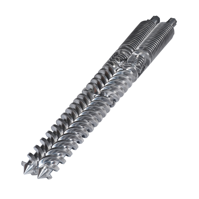
Define the Profile Before Specifying the Screw and Barrel
Send the cross-section with the dimensions that determine acceptance. Identify visible faces, main walls, internal ribs, hollow chambers and any mating or sealing features. Include the required straightness, surface appearance and mass per meter. A photograph shows the application; a controlled drawing defines what must be reproduced.
State whether the profile is solid, hollow, foamed or coextruded. For a multilayer construction, provide the layer arrangement and the compound supplied by each extruder. Total profile weight cannot establish the material demand of a thin cap layer or a separate sealing feature.

| Profile requirement | Record with the inquiry | Why it matters |
|---|---|---|
| Hollow frame or structural section | Critical walls, ribs, dimensional tolerances and required product tests | Output must remain usable after forming, calibration and cooling |
| Visible trim or molding | Appearance samples, color, surface marks and mass per meter | Melting, distribution and deposits need separate investigation |
| Thermoplastic seal | Grade, section, dimensional and functional requirements | Material preparation and support of the hot profile affect the trial |
| Coextruded profile | Layer drawing, compound per unit and individual material rates | Each screw has its own feeding and plasticating duty |
Define acceptance against the applicable product specification. For example, EN 12608-1:2026, published in Germany as DIN EN 12608-1:2026-10, addresses non-covered PVC-U profiles for windows and doors. Its scope does not extend to every trim or seal, and it is not a screw-manufacturing standard.
Match the Compound and Feed Form to the Installed System
“PVC profile” is an application label, not a complete formulation. Record resin grade, stabilizers, lubricants, processing aids, fillers, pigments and any regrind. Specify whether ingredient quantities are expressed in parts per hundred resin or percentages of total compound.
For example, 30 phr calcium carbonate means 30 parts filler per 100 parts PVC resin. It does not mean 30 wt% of the finished compound. Even the two-component calculation is 30 ÷ 130, or about 23.1 wt%; other ingredients change the denominator. Keep the original formulation basis visible when comparing proposals.
PVC dry blend, prepared pellets and other thermoplastics
Dry blend and prepared pellets differ in feed form and processing history. For PVC, discuss the required plasticating and fusion behavior with the compound and equipment suppliers. Do not transfer a polyolefin pellet-melting description unchanged to a PVC dry-blend screw.
Equipment OEM battenfeld-cincinnati distinguishes PVC window and WPC/NFC profiles from other technical profiles, listing conical or parallel twin-screw equipment for the former and single- or twin-screw routes for technical profiles. This supports identifying the actual material route rather than choosing an architecture from the word “profile” alone.
For thermoplastic elastomers, identify the polymer family and exact grade. Lubrizol's TPU extrusion processing guide requires drying before processing and directs users to grade-specific instructions. Its profile section also discusses melt strength and cooling. Those recommendations belong to Lubrizol TPU; they cannot be applied to every thermoplastic seal or to vulcanizing rubber.
Record regrind and each coextrusion stream separately
Include regrind source, feed form, proportion and handling. A change in particle form or formulation can alter feeding and plasticating even when the base-polymer name stays the same. Retain samples and lot records when comparing a current screw with a proposed replacement.
On a coextrusion line, document the main profile, cap layer and any soft feature separately. Include the normal rate and operating range of each unit. A material change in one layer should trigger a review of that layer's screw duty and the combined product trial.
Review Extrusion Screw Design and Compression Ratio for Profile Production
An extrusion screw must accept the feed, provide the required plasticating and deliver material to the die within the machine's limits. A proposal should explain which of those tasks needs improvement and which dimensions or functional sections will change.
Interpret ratios with the complete working geometry
For a conventional single screw with constant pitch and comparable channel widths, feed-channel depth divided by metering-channel depth approximates geometric compression ratio. A change in pitch or channel layout needs a volume-based comparison. This shortcut is not a design rule for an intermeshing conical twin-screw pair.
Review channel-depth progression, transition length, pitch, flight geometry and any mixing section together. L/D describes the available working length relative to diameter; it does not establish residence time by itself. See the EJS compression-ratio guide for the geometric distinction.
Higher compression or a longer screw can change plasticating, pressure and mechanical heat input. Neither is a universal cure for a rough profile surface. Ask the supplier to relate a proposed change to the compound, operating range and identified defect.
Separate melting, mixing and venting requirements
A mixing section needs a defined task: distributing color, reducing thermal nonuniformity or addressing a demonstrated dispersion problem. Identify the defect before specifying more restrictive mixing. A black speck from degraded or foreign material is a different problem from an incompletely plasticated particle.
The Lubrizol TPU guide recommends barrier geometry and an end-of-screw mixing section for its materials, together with effective thermal control. That material-specific guidance illustrates why a barrier screw proposal should be evaluated against a defined duty rather than treated as an upgrade for every profile compound.
Where venting is required, include its location, feed conditions, vacuum system and the approved operating range. Venting does not automatically replace the material supplier's drying procedure. Keep actual melt measurements separate from barrel-controller setpoints.
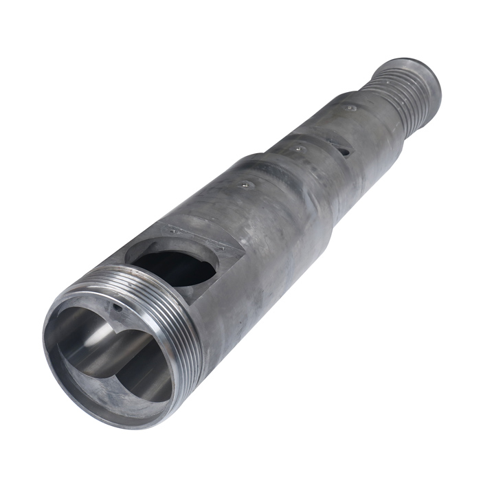
Diagnose Profile Defects and Extruder Screw Wear Issues
Record where a defect appears around the cross-section and how it changes along the profile. Keep samples in production order and connect them to time-stamped process readings. This distinguishes a persistent local mark from an output fluctuation affecting successive lengths.
| Observation | Check alongside the screw | Useful evidence |
|---|---|---|
| Line at a fixed position on the surface | Die condition, deposits and contact with downstream equipment | Marked cross-section and samples showing the same position |
| Periodic mass or dimensional variation | Feeding, drive behavior, pressure, puller speed and calibration | Synchronized readings and sequential weighed lengths |
| Bubbles or roughness | Material preparation, actual melt condition, venting and tooling | Grade/lot records, preparation history and identified defect samples |
| Discoloration or black specks | Contamination, deposits, retained material and thermal history | Startup/steady-run comparison and located deposit photographs |
| Bowing or dimensional drift | Temperature distribution, cooling, calibration and haul-off | Measurements tied to position, time and downstream conditions |
A screw-wear diagnosis needs component measurements and process history. A pressure trace alone is insufficient. In its PVC flow-pulsation explanation, battenfeld-cincinnati describes fluctuations associated with the C-shaped chambers in counter-rotating twin screws, particularly at low output for small technical profiles. A repeating signal can therefore have a structural processing cause without proving excessive wear.
Convert a repeating spatial pattern into a time interval before comparing it with the process log. At a steady 5 m/min, marks spaced 1 m apart correspond to 12 seconds between events. This kinematic example provides a timing reference, not a diagnosis; compare the interval with recorded feeding, drive and downstream behavior.
Likewise, a steady extruder pressure does not prove that downstream calibration and traction are stable. Check the complete chain before authorizing a redesign. Make operating changes only within the equipment and material suppliers' approved procedures.
Measure the screw and barrel at corresponding locations
For a single circular bore, diametral clearance is barrel ID minus the corresponding screw flight OD; radial clearance is half that difference. Identify which convention the drawing uses. Twin-screw inspection also requires the actual intermeshing geometry and approved measurement procedure, not one scalar clearance copied from a single-screw example.
Record axial locations, measurement orientations, surface condition and the new-part baseline. If the barrel is retained, its current dimensions belong in the replacement review. Use the EJS wear-monitoring guide to connect repeat measurements with spare-part planning.
Select Working Surfaces from the Actual Failure Mechanism
Separate material removed by abrasion, chemically attacked surfaces and damage associated with mechanical contact. Filler identity, loading, contamination, process history and the location of damage matter more than a generic request for a “harder screw.” A change in working material cannot correct an unresolved alignment or interference problem.
EJS's profile product page lists nitrided and Ni60-hardfaced options, along with Colmonoy grades. Use the EJS materials guide to distinguish the base steel, surface treatment and working alloy. Specify screw and barrel protection separately.
| Evidence | Review in the proposal |
|---|---|
| Progressive flight or bore wear | Protected locations, working material, remaining substrate and mating dimensions |
| Pitting or roughened surfaces | Compound and cleaning chemistry, thermal history and affected areas |
| Localized scoring or contact marks | Straightness, installation, support and approved operating clearances |
| Chipping or loss of a working layer | Layer integrity, substrate support and the cause of the damage |
Surface hardness and hardened-layer depth describe different properties. ISO 18203:2026 addresses measurement of surface-hardened layer thicknesses, including nitriding hardness depth. Where that method is specified, identify the measured property and acceptance criterion; it does not set one universal screw case depth or service life.
For a hardfaced construction, also define coverage, thickness, finished geometry and inspection requirements. Flight protection cannot restore a worn mating barrel. Compare the proposed screw and barrel as an installed combination before comparing their prices.
Check Extruder Screw Replacement Fit and Required Output
State material demand from the actual profile rather than the machine's maximum advertised output. For a single-material product, finished mass per meter multiplied by line speed gives the finished-product mass rate. Startup scrap, rejected lengths and any separate material streams need their own accounting.
Assumed finished mass per meter
Assumed speed, converted to hours
Finished-product material rate
These are illustrative inputs, not machine ratings or production results. Establish separate rates for coextruded materials.
This calculation defines a demand point. It does not size the screw or prove that the die, calibrator, cooling and haul-off can sustain it. Record the lowest required rate as well as the target rate, especially when one line produces several cross-sections.
Confirm fit from controlled drawings
An extruder screw replacement needs more than nominal diameter. Identify flighted and overall lengths, drive connection, axial location, tip/end geometry, rotation and all mating interfaces. For a twin-screw assembly, include the pair arrangement, center-distance or taper information and installation references required by the OEM.
On the barrel, confirm bore geometry, feed and vent openings, flange details, mounting positions and heating/cooling interfaces. Do not assume that the same diameter or nominal model code establishes interchangeability. Keep retained-part measurements attached to the approved drawing revision.
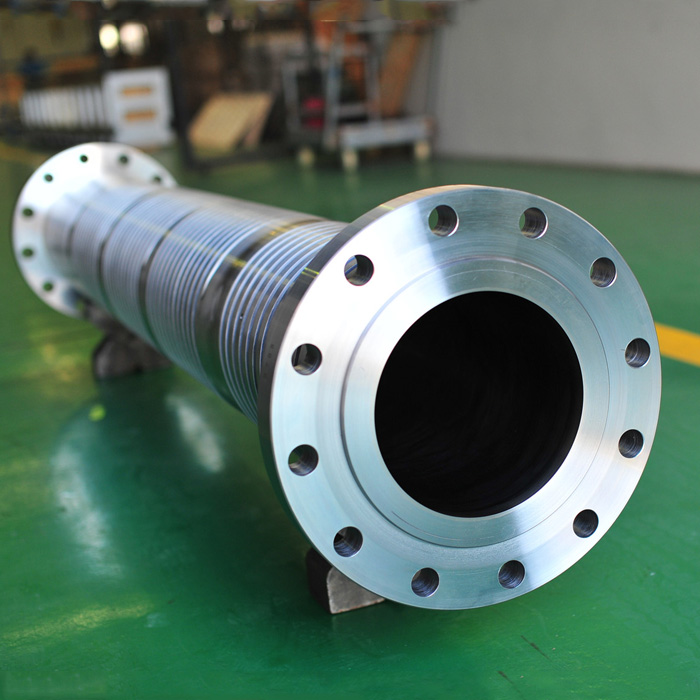
Validate the Replacement on Accepted Profile Production
Agree on the trial before changing the hardware. Use a controlled material formulation and preparation method, an identified die and calibration setup, and a defined sampling plan. Record screw speed, load, pressure, actual melt temperature, line speed and finished-product results over the same intervals.
The factory perspective: connect the drawing to the trial record
For a mineral-filled PVC profile, our recommended review starts with the compound record and installed geometry. Where inspection confirms progressive abrasive wear, compare protection at the flights, channel surfaces and barrel bore. Keep the existing wear map with the proposed drawing so that a material upgrade is assessed against the condition of every retained part.
Before accepting a change, require both dimensional conformity of the supplied components and satisfactory profile production. The component inspection and the extrusion trial answer different questions. Compare the finished dimensions, mass per meter and surface quality at the agreed operating points; record startup losses and rejected lengths separately.
| Record | What it establishes | What to compare |
|---|---|---|
| Component inspection | Conformity to the approved part specification | Geometry, interfaces, specified working materials and inspection results |
| Stable production samples | Profile quality at the recorded conditions | Critical dimensions, appearance, mass per meter and required product tests |
| Production log | Accepted output over the sampling period | Accepted meters, rejected material, interruptions and actual process readings |
| Follow-up measurements | Condition after a documented exposure | Matched locations, processed formulation and accumulated operating record |
Calculate the economic threshold before claiming a longer life
Use installed component cost divided by accepted profile length before replacement. In an illustrative comparison, a 40% installed-cost premium needs more than 1.40 times the accepted length to lower that unit cost. If accepted length reaches 1.75 times the baseline, the ratio is 1.40 ÷ 1.75 = 0.80: component cost per accepted meter is 20% lower.
Those are conditional calculations, not measured service-life improvements. Converting the accepted-length ratio into an operating-hours multiplier also requires equal accepted production rates. Energy, downtime, financing and other costs need separate entries before this becomes a total-cost comparison. An alloy name or hardness reading cannot supply the missing production data.
Frequently Asked Questions
Can one screw process every profile material?
A screw may cover an agreed material range, but suitability depends on grade, feed form, formulation, operating rate and quality requirements. Review each proposed material change against the actual geometry, machine limits and production trial.
Does dimensional variation mean the extruder screw is worn?
No. Feeding, flow pulsation, material preparation, die conditions, calibration, cooling and haul-off can also affect dimensions. Correlate samples with process readings and component measurements before assigning the cause to wear.
Will a higher compression ratio improve profile surface quality?
Only if the proposed geometry addresses a confirmed plasticating limitation within the material's thermal window. Surface defects can have other causes. Review compression ratio with the complete working profile rather than treating a higher value as an automatic improvement.
Can a replacement screw fit if the diameter is the same?
Matching diameter is insufficient. Confirm lengths, drive connection, axial location, rotation, end geometry and mating interfaces. Twin-screw parts also require the correct pair geometry and installation references. Check the condition and dimensions of retained components.
What information is needed for a profile screw and barrel quotation?
Provide the cross-section drawing, compound and formulation basis, feed form and regrind details, machine and component drawings, current wear measurements, operating records and required acceptance criteria. For coextrusion, identify each unit and its material rate separately.
Prepare a specification that can be checked
Send EJS the profile drawing, material record, installed-part drawings and the problem to resolve. Its product information states that supplied screw barrels include an inspection report and material certificate. Agree on the component specification and production acceptance plan together.