A customer sends a drawing marked 30:1, compression 3:1, and asks us to copy it. Nine times out of ten we do exactly that. The tenth time, we ask what they feed the machine — and the answer explains the problem they have been living with for two years.
L/D ratio and compression ratio are the two numbers everyone quotes and almost nobody interrogates. They are genuinely useful. They are also incomplete in ways that cost output every day. Rather than define them and stop, here are three situations that come across our benches repeatedly, and what each one reveals about what the numbers do and do not control.
Case 1 — The screw that was "correct" and still surged
Output down, pressure surging, spec unchanged
The screw specification was fine. It had been fine when it was designed. What had changed was upstream: the plant had started blending its own edge trim back into the feed. On paper nothing about the screw was wrong — the drawing still said 30:1 and 3:1, exactly as before.
But compression ratio is not an abstract quality rating. It is a statement about how much air has to come out of the feed. Dense virgin pellets carry relatively little; irregular film flake carries a great deal more, and it does not pack the same way in the feed channel. The screw was being asked to do a job it was never dimensioned for.
What L/D actually buys you
Take the definition first, briefly, because the cases depend on it. L/D is the screw's effective flighted length divided by its outer diameter — a 90 mm screw with 2,700 mm of flighted length is 30:1. Being a ratio, it transfers across machine sizes: 30:1 at 60 mm and 30:1 at 150 mm give proportionally the same working length.
Common L/D ratios for screw extrusion typically range from 20:1 to 30:1, and the drive for throughput and mixing has pushed modern designs commonly to 30:1 or more. What length buys is residence time — more turns of screw in which to convey, melt, mix and build pressure.
A counting quirk worth knowing before you compare quotes
Square-pitch screws make L/D easy to read off by counting turns, but there is a convention people apply inconsistently. The portion under the feed opening should not be included in L/D — though many people do count it, because it makes the screw appear longer. If two suppliers quote different L/D for what should be the same part, this is the first thing to check.


Longer is not a free upgrade. More length is more residence time and more shear history. On rigid PVC, time at temperature is precisely what produces degradation. A longer screw also costs more and demands more torque. Length helps when length was the constraint — not otherwise.
Case 2 — When the recycling line started
Feeding problems that appeared out of nowhere
This is Case 1's twin, and it is common enough that it deserves naming. A screw designed around dense free-flowing pellets, later fed a substantial share of film flake or regrind, has two problems at once: the feed channel does not fill consistently, and there is far more entrained air to drive back out than the compression profile was built to handle.
The symptoms — surging, erratic output, longer purge times — look like machine faults, which is why the diagnosis often goes down an expensive dead end first. Nothing is broken. The screw is simply doing a different job than the one it was drawn for.
| Feed form | Bulk density | What it demands of the screw |
|---|---|---|
| Dense free-flowing pellets | High | Less compression; feeding is rarely the constraint |
| Powder / dry blend | Low | More compression; large feed area matters |
| Film flake or regrind | Very low, irregular | More compression, and feeding itself becomes the limit |
| Heavily filled compound | Varies | Set by melting behaviour and heat tolerance |
| Rigid PVC dry blend | Low | Needs compression, but degrades if it comes too fast |
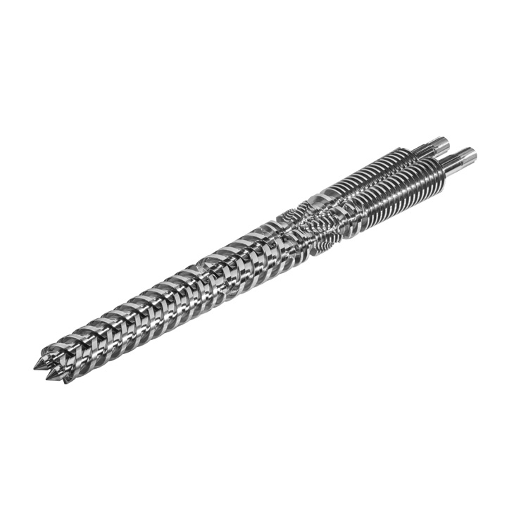
That last row is why rigid PVC ends up on conical twin screw barrels rather than being solved with a compression number: the taper compresses progressively along the whole length instead of in one step. We design those differently again depending on whether the compound is low, medium or high CaCO₃ — covered in screw barrels for PVC extrusion.
What compression ratio measures
Formally, the compression ratio is the ratio of the volume of the first flight to the volume of the last one, usually between two and four, and on a constant-pitch screw it is often taken as the ratio of first to last channel depths.
In workshop terms: as material melts it loses the air between the granules and takes up less room, so the channel has to shallow to keep the melt compacted and push that air back toward the hopper. Too little compression leaves unmelt and entrained air. Too much converts your motor current into shear heat you then have to remove.
Working it out from a screw you have in front of you
- Feed channel depth = (outer diameter − root diameter at the feed zone) ÷ 2
- Metering channel depth = (outer diameter − root diameter at the metering zone) ÷ 2
- Compression ratio ≈ feed depth ÷ metering depth
This depth figure approximates the true volumetric ratio. Where pitch varies along the screw, the two diverge — which is the first hint that the headline number is doing less work than people assume.
Case 3 — Same ratio, different screw
Two 3:1 screws that behaved nothing alike
Compression ratio tells you how much the channel shallows. It says nothing about how fast. Achieve 3:1 gradually across a long transition and the material is compressed gently. Achieve the identical 3:1 across a handful of flights and you concentrate the same volume reduction into a short distance — with the shear heat that implies.
Both screws are honestly described as "3:1." Only one suits a heat-sensitive material. The variable that separated them — the split of total length between feed, transition and metering — appears in neither headline number, only on the drawing.
The blind spots in both numbers
We would rather say this plainly than let a buyer over-trust a figure. As one long-standing extrusion reference puts it, compression ratio is useful, but it is an indefinite number that cannot on its own describe how a screw will behave.
Neither L/D nor compression ratio tells you:
- The zone split — Case 3 in one line
- The pitch profile — constant or varying, and where it changes
- Mixing sections — a Maddock, Pineapple or Saxton element moves melt quality further than a small compression change
- Clearance — the screw-to-barrel gap governs output, and it widens as the set wears
- Surface treatment — nothing in the geometry says whether the part survives your filler
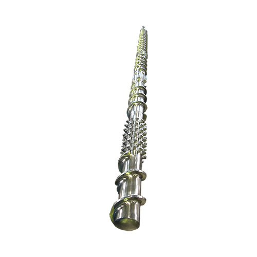
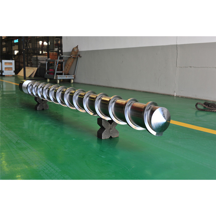
That final point is where money is lost quietly. Geometry governs performance on day one. The material and surface treatment govern how long day one lasts. A well-designed screw in the wrong alloy still wears out early in a filled compound — and then the clearance opens, and the geometry you paid for stops mattering.
What you can change on your machine — and what you cannot
Worth being clear about, because it determines what is even worth discussing.
L/D is fixed. The barrel length, the frame and the drive are built around it. There is no longer screw for your existing extruder; that is a different machine.
Nearly everything else is open. Zone split, channel depths and therefore compression ratio, pitch, mixing sections, surface treatment — all specified per job, because screw barrels are close to 100% customized anyway. At our Zhoushan shop that runs from 12 mm to 500 mm diameter, working lengths to 10,000 mm, with the feed housing, feed liner and water jacket made in-house alongside the screw.
The one moment when changing the design is free
- Replacement is when a geometry that never suited the feedstock can be corrected at no extra tooling cost
- Copying a worn screw exactly also copies whatever was wrong with it
- If output, unmelt, surging or degradation has been a standing complaint, put it in the inquiry instead of ordering a duplicate
No drawing is normal for replacement work — photos plus diameter, length and flange details are enough to begin, and our engineers can measure an existing screw barrel on site whatever the machine brand. Every part ships with a material certificate and inspection report, built to Ra 0.4 µm surface roughness and 0.015 mm straightness.
Questions we get asked
What is the L/D ratio of an extruder screw?
L/D is the screw's effective flighted length divided by its outer diameter. A 90 mm screw with 2700 mm of flighted length is 30:1. Common single screw extrusion values run about 20:1 to 30:1, with modern designs often extending to 30:1 or more. One detail worth checking when comparing suppliers: the portion under the feed opening should not be counted, though many people include it because it makes the screw appear longer.
What is compression ratio on an extruder screw?
It is the ratio of the volume of the first flight in the feed zone to the volume of the last flight in the metering zone, usually between two and four. On a constant-pitch screw it is often taken more simply as the ratio of feed channel depth to metering channel depth. It measures how much the material is compacted as it melts and as trapped air is driven back toward the hopper.
Why do two screws with the same compression ratio perform differently?
Because compression ratio says how much the channel shallows, not how fast. The same ratio achieved gradually over a long transition zone is far gentler than the same ratio squeezed over a few flights, which concentrates shear heat. The zone split between feed, compression and metering is what separates the two, and it does not appear in either headline number.
Does adding regrind require a different screw design?
Often yes. Compression requirement follows the bulk density of the feed, not the polymer name. A screw designed around dense virgin pellets and later fed 20 to 30 percent film flake is being asked to remove far more entrained air than it was built for. Feeding problems, surging and output loss that begin after a recycling programme starts are frequently a screw design mismatch rather than a machine fault.
Can I change the L/D ratio on my existing extruder?
No. The barrel length, frame and drive are built around it, so L/D is fixed by the machine. What can change on a replacement screw is the zone split, the channel depths and therefore the compression ratio, the pitch, the mixing section and the surface treatment. That is where real improvement is usually available.
What should I tell a screw manufacturer besides L/D and compression ratio?
The machine make and model, screw diameter, the polymer with filler type and percentage, the physical form of the feed such as pellet, powder, flake or regrind and its proportion, the output target, and the specific problem you want solved. The feed form and filler content change the design more than the headline ratios do.
Is a higher L/D ratio always better?
No. More length gives more residence time, which helps when melting or mixing is the limiting factor and improves melt uniformity. But it also means more shear history and longer time at temperature, which degrades heat-sensitive materials such as rigid PVC, and it costs more and demands more torque. Length helps only when length is what the process was short of.
Sources & references
- PlasticsToday — Extrusion Basics: The Taming of the Screw (L/D counting convention, compression ratio definition and range)
- Dr. D Flo — Screw Extrusion Basics: Fundamentals and 3D Printing Applications (common L/D range, screw zones, clearance)
- Polymers (MDPI) — Design, Modeling, and Validation of a Compact, Energy-Efficient Mixing Screw (trend toward higher L/D)