- English
- 简体中文
- Español
- Português
- русский
- Français
- 日本語
- Deutsch
- tiếng Việt
- Italiano
- Nederlands
- ภาษาไทย
- Polski
- 한국어
- Svenska
- magyar
- Malay
- বাংলা ভাষার
- Dansk
- Suomi
- हिन्दी
- Pilipino
- Türkçe
- Gaeilge
- العربية
- Indonesia
- Norsk
- تمل
- český
- ελληνικά
- український
- Javanese
- فارسی
- தமிழ்
- తెలుగు
- नेपाली
- Burmese
- български
- ລາວ
- Latine
- Қазақша
- Euskal
- Azərbaycan
- Slovenský jazyk
- Македонски
- Lietuvos
- Eesti Keel
- Română
- Slovenski
- मराठी
- Srpski језик

Injection Molding Screws and Barrels for Glass-Filled Plastics
Choose injection molding screws and barrels for glass-filled plastics by defining the complete formulation, specifying protection for each component and checking the mating parts. Glass content helps establish the duty, but the base polymer, fiber length, additives, processing conditions and required part properties also affect the choice.
Review the screw, barrel and non-return assembly together. Then verify both processing quality and the condition of the components in service.
A request for a screw to run glass-filled nylon often arrives with a machine model and a filler percentage. That is a useful start. It leaves several questions open: Is the problem abrasive wear, unstable metering, damaged fibers, or a worn mating barrel? Does the replacement need different metallurgy, different geometry, or both?
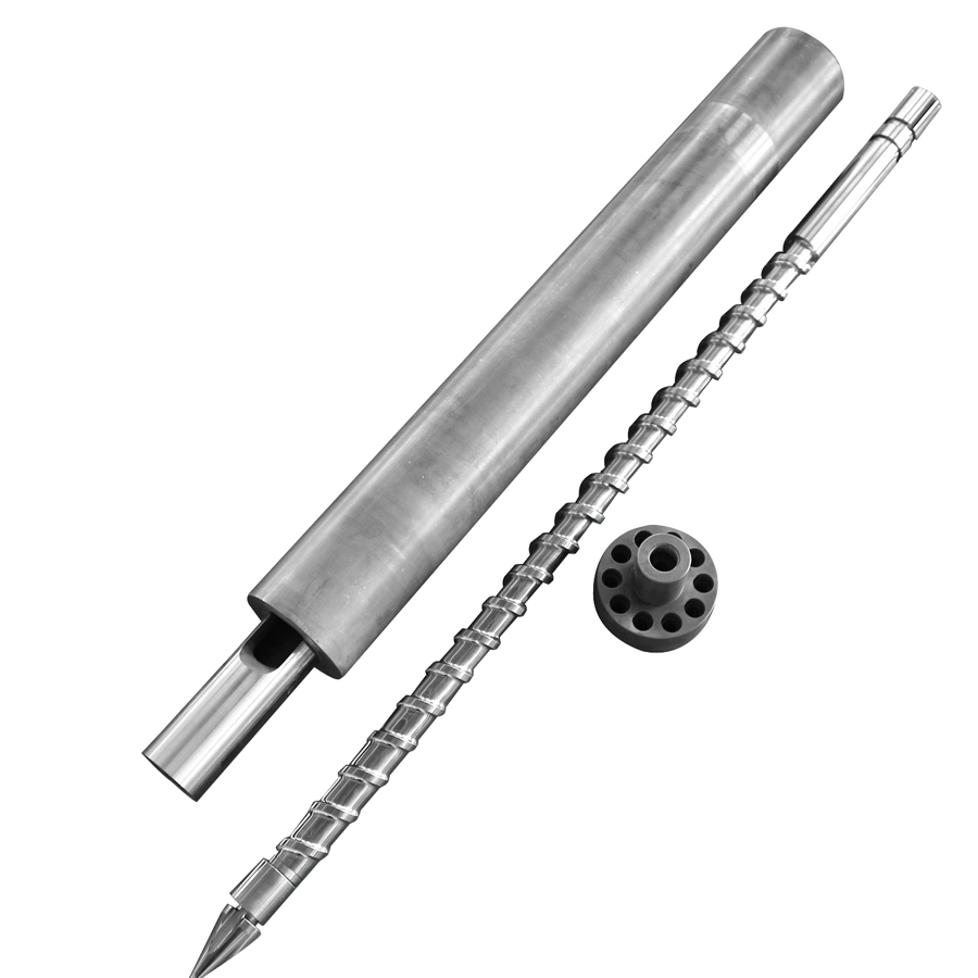
The purchasing decision becomes clearer when those questions are separated. EJS's injection molding feed screws are made to supplied drawings, with material and treatment options for different duties. An injection molding feedscrew recommendation should therefore connect the material being processed to a defined component specification and an acceptance plan.
Start with the Complete Glass-Filled Resin Specification
Base polymer, grade and glass content
Ask for the resin manufacturer's full grade designation and processing data. PA6, PA66, PBT and PP are different starting points, even when the quoted glass percentage is the same. Confirm whether the stated percentage is a mass fraction and whether it describes the supplied compound or the final blend.
A label such as PA66-GF30 does not identify the entire formulation. The actual grade can include stabilizers, flame retardants, lubricants or other fillers that change the review. Record the current material rather than copying the specification from an earlier order.
Short glass fiber versus long glass fiber
Identify the reinforcement system and pellet form. Long-fiber material introduces a specific question: how will the plasticizing unit melt and convey the compound while preserving the reinforcement needed by the part? A mixing feature selected for a different task may need a fresh review.
Additives, regrind and the production mix
Include other fillers, the known additive package, regrind source and proportion, and whether the machine regularly changes materials. For proprietary formulations, share the required processing and compatibility information through the agreed confidential channel.
Resin identification card
Manufacturer and grade · glass content and basis · short or long fiber · additives/other fillers · regrind source and proportion · current processing sheet · part-quality requirements
Why Injection Molding Screws Wear Out with Glass-Filled Plastics
Abrasive duty is a reason to review wear protection. It does not explain every damaged surface. Examine the location and character of the damage before choosing a harder material or changing the profile.
Abrasive wear on flights, roots and the barrel bore
Record flight outside diameters, root condition, flight edges and the corresponding barrel locations. Protection confined to the flight lands does not describe the condition or protection of the root. The measurement map should show which surfaces are losing material.
Corrosion and additive-related attack
Check the formulation's chemical compatibility separately from its abrasive content. A flame-retardant label alone does not establish one corrosion level for every grade. The material supplier's advice and the observed surface condition should guide that review.
Scoring or galling needs a mechanical review
Localized scoring, interference or a damaged flight also calls for checks of the mating parts and installation. A material change cannot establish correct straightness, alignment or fit. Preserve the wear pattern and inspection records before repair changes the evidence.
Use the screw and barrel wear-measurement guide for the broader inspection method. This review adds the formulation and component-protection requirements specific to the glass-filled application.
Separate Component Wear from Material and Process Problems
Process symptoms help decide what to inspect. They do not identify a failed component on their own. Compare the present job with its stable baseline before attributing every change to screw wear.
| Observed change | Check alongside component wear | Useful evidence |
|---|---|---|
| Longer or variable recovery | Feed consistency, resin preparation, temperature, speed/back-pressure changes and the actual shot requirement. | Comparable recovery records, settings and measured screw/barrel condition. |
| Cushion or shot-weight variation | Non-return-valve condition and behavior, process sequence and material consistency. | Repeatability records and an inspection of the complete front-end assembly. |
| Splay, discoloration or black specks | Material preparation, thermal history, retained material and other contamination sources. | Moisture/preparation records, actual melt condition and component examination. |
| Unexpected part-property loss | Material identity, preparation, fiber condition, molding conditions and test-specimen conditions. | Agreed product tests and a controlled process comparison. |
For a specific example, BASF's Ultradur brochure, page 28, connects a marked cushion reduction during holding with a need to check non-return-valve sealing or excessive play. That is guidance for its PBT processing context, not a diagnosis of every unstable shot.
A replacement proposal should state which finding it addresses. If material preparation explains the defect, changing the screw's working alloy does not resolve that preparation problem.
Injection Molding Screws and Barrels: Specify Wear Protection by Component
Ask for a component specification with named working surfaces. A quotation that says only “bimetallic screw barrel” leaves the alloy, coverage, mating relationship and inspection basis unclear.
THREE COMPONENTS · THREE SPECIFICATIONS · ONE ASSEMBLY
SCREWSupport and working surfaces
Identify the core, flight protection, root treatment and final profile.
BARRELStructure and working bore
Identify the body, lining or treatment, finished bore and interfaces.
VALVEFlow and closure
Identify each mating part, its material, flow passage and sealing geometry.
Screw core, flight hardfacing and other working surfaces
Separate the structural material from any local working alloy or surface treatment. Specify where protection is applied, including what happens at the flight edges and root. Final dimensions and the intended profile remain part of the order.
EJS's bimetallic screw product page describes alloy welded into the flights and notes that the geometry must allow the process. A drawing review is therefore needed before assuming any screw can receive the same construction.
Barrel lining and mating surfaces
Specify the bore's working material separately from the barrel body. EJS lists centrifugal-cast inlay and carbide-liner constructions on its bimetallic barrel page, with manufacturing feasibility dependent on the barrel dimensions. Confirm the proposed construction for the actual drawing.
The valve deserves its own line on the specification. The screw, barrel and valve can use different materials selected for their respective work; each mating relationship still needs review.
Why hardness alone does not complete the specification
The January 2023 EMS-GRIVORY polyamide guide, page 4, separates screw, cylinder and backflow-valve materials. Its wear-protection categories consider filler content together with corrosion tendency. This is a material-specific framework, not a universal glass-percentage cutoff or an EJS alloy prescription.
Compare the material designation, heat treatment, protected area, final geometry and agreed inspection evidence. For a nitrided option, ISO 18203:2026 covers measurement of surface-hardened-layer depths, including nitriding hardness depth. It does not establish one acceptance depth or service life for every injection screw.
The screw and barrel materials guide explains the distinction between substrate, treatment and working alloy in more detail.

Match the Protection Strategy to the Formulation
Use an application matrix to organize the review. Its purpose is to identify the evidence needed for a recommendation, rather than assign one alloy to every polymer family.
| Application | Establish first | Component review | Validation focus |
|---|---|---|---|
| Glass-filled PA6 or PA66 | Full grade, fiber system, preparation requirements, additives and duty. | Screw working surfaces, barrel bore and valve materials considered together. | Stable preparation and metering, product properties and wear records. |
| Short-glass-filled PP | Compound identity, glass content, other fillers and mixing task. | Wear protection plus geometry appropriate to the actual compound. | Melt uniformity, acceptable recovery and part requirements. |
| Long-glass-filled PP or polyamide | Supplier's long-fiber processing instructions and reinforcement target. | Melting profile, restrictive passages, shear features and wear protection. | Required fiber-related properties alongside stable molding. |
| Glass-filled PBT | Grade-specific preparation, thermal history and front-end requirements. | Wear-resistant screw, barrel and valve options within the grade's guidance. | Material condition, sealing, part quality and service measurements. |
| Flame-retardant or higher-temperature grades | Actual formulation, processing window and compatibility advice. | Chemical resistance and thermal duty as well as abrasion. | Grade-specific quality, equipment limits and surface condition. |
For glass-reinforced Ultradur PBT, BASF explicitly calls for hard-wearing steels in the cylinder, screw and non-return valve. The useful lesson is to review the whole plasticizing path. A recommendation for that PBT family does not select the alloy for an unrelated PA or PP grade.
When the same machine runs several compounds, list the representative jobs. A configuration selected around one formulation also needs an agreed operating range for the others.
Balance Melting and Mixing with Fiber Retention
A wear-resistant screw does not automatically need a new profile
Changing metallurgy and changing geometry solve different questions. If the existing profile meets the processing task, specify what should remain. If melting or mixing is inadequate, identify the feature to change and the result that will be checked.
More mixing can be the wrong change for long fibers
The EMS-GRIVORY long-fiber guide, July 2011, page 2, advises against additional mixing and other shear elements for the long-fiber polyamides it names. Keep that application scope: this does not prohibit all mixing features for every glass-filled resin.
Define whether the task is melt preparation, color distribution or reinforcement preservation. The selected profile must satisfy the required combination. A uniform appearance alone does not verify the mechanical properties of a reinforced part.
Compression ratio for glass-filled injection molding screws
Asahi Kasei's Polypropylene Processing Guidelines, PDF page 4, gives different guidance for short-fiber/mineral-filled PP and long-fiber PP:
| Scope in the Asahi Kasei PP guide | Suggested compression ratio |
|---|---|
| PP formulations, including short glass fiber and minerals | 2.4:1 to 4.0:1 |
| Long-fiber PP | 1.8:1 to 2.5:1 |
These are that guide's PP recommendations. They illustrate why the reinforcement system matters; they are not universal limits or EJS manufacturing specifications. Confirm the current grade and complete profile with the resin and equipment suppliers.
The separate extrusion screw compression ratio guide explains geometric definitions in continuous extrusion. Apply those definitions carefully when reviewing a reciprocating injection screw and its metering stroke.
Injection Molding Screw Tip and Check Ring: Flow and Wear Checks
The injection molding screw tip and non-return assembly must pass the material during recovery and provide the required closure during injection and holding. Review those functions separately.
Check flow passages, valve travel and mating parts
Identify the ordered tip, ring, seat and any other components on the actual assembly drawing. Record the flow path, opening travel, sealing surfaces and materials. A matching external diameter does not prove that the internal flow path suits the compound.
For its specified long-fiber polyamides, the EMS LFT guide, page 3, calls for sufficient passage beneath the valve ring and sufficient travel; it generally advises against ball backflow valves for those products. That is a formulation-specific review point, not a universal ranking of valve types.
Give the front end its own wear specification
EJS supplies different screw-tip and non-return assemblies, including options for high-wear applications. Confirm the appropriate design and working materials for the order. Use the screw-tip assembly guide for component identification and interface checks.

Review Screw Speed, Back Pressure and Thermal History
Compare peripheral speed as well as RPM
The same RPM gives different outside-surface speeds at different screw diameters. The geometric conversion is:
Peripheral speed v = π × D × N ÷ 60,000
D is screw diameter in mm; N is speed in rpm; v is outside-surface speed in m/s.
HYPOTHETICAL SPEED COMPARISON · COMMON 0 TO 0.419 m/s SCALE
Use the lowest adequate back pressure for the confirmed duty
For the long-fiber polyamides covered by its guide, EMS recommends moderate screw speeds and low, sufficient back pressure to limit unnecessary shear and fiber damage. The target remains a stable melt and metered charge. “Low” must be interpreted within the actual process, rather than converted into a blanket zero setting.
Record whether a displayed pressure is hydraulic-side or plastic-side, its units and any conversion. This prevents a misleading comparison between trials on different injection units.
Measure melt conditions as well as heater settings
Asahi Kasei's PP guide notes that melt temperature depends on the profile, RPM, residence time and equipment geometry. Treat heater settings as inputs to the process; verify the resulting melt condition using the appropriate method for the resin and equipment.
Check whether recovery fits the actual machine sequence. Faster recovery is useful only in relation to melt quality, equipment limits and the available cycle window. The diameter and shot-capacity guide covers the separate injection-unit sizing review.
Injection Molding Barrel Condition and Replacement Fit
A new screw still runs in the existing barrel
For an injection molding barrel retained in service, establish the actual bore condition along the working length. Keep those measurements separate from the original drawing. The old screw is also a record of wear, rather than a complete statement of the required new dimensions.
Check mechanical interfaces before selecting a material upgrade
Confirm the drive, threads, axial references, working length, front-end components and barrel connections. Review the proposed profile against the injection unit's speed, load and pressure limits. A machine model helps identify the assembly; the applicable drawing and configuration complete the definition.
How I would review the replacement
When reviewing a screw and barrel for glass-filled material, I would first check the full grade, glass content, short- or long-fiber system, flame-retardant package and regrind. I would not select an alloy from the description “glass-filled nylon” alone.
If recovery slows or the cushion becomes unstable, I would examine preparation, the non-return assembly and screw/barrel measurements separately. Drawing dimensions and worn-part measurements need separate records, because a new screw may still run inside a worn barrel.
Once the material direction is clear, I would list the screw core, flight and root protection, barrel working layer and front-end requirements individually. A quotation saying only “bimetallic” leaves too much unresolved. For long fibers, I would also check the passages and mixing features before adding shear in pursuit of uniformity.
Finally, I would require actual melt temperature, load, shot weight and product-quality records from the trial, together with a dimensional baseline. An acceptable short trial establishes processing fit at that time. Wear performance needs subsequent records under comparable conditions.

Validate the Selection and Track Cost in Service
Separate restoration of worn hardware from changes to geometry or metallurgy. If several things change at once, the trial evaluates the combined proposal. It does not isolate the contribution of one alloy.
The EMS polyamide guide, page 5, recommends coordinating component materials and design with the machine supplier. That coordination matters when comparing replacement assemblies as well as material options.
A first-person review of two replacement options
Consider a hypothetical nominal 60 mm injection unit processing PA66-GF30. I would compare the barrel bore and screw outside diameter at the same axial position. Assume a measured old bore of 60.16 mm and an old screw OD of 59.76 mm. For concentric circular geometry, the nominal radial clearance is (60.16 - 59.76) ÷ 2 = 0.20 mm.
If I replace only the screw with a 59.94 mm OD part, the same calculation gives 0.11 mm. If a paired barrel in the second proposal has a 60.00 mm bore with that screw, the result is 0.03 mm. Every dimension here is assumed for this example; none is a general manufacturing tolerance or rejection limit.
HYPOTHETICAL LOCAL CLEARANCE · COMMON 0 TO 0.20 mm SCALE
I would review both proposals alongside the wear map, rather than decide from the new screw's alloy name. The calculation establishes a local geometric difference between the options. Choosing the assembly still requires the original drawing, other wear locations, the formulation and actual assembly conditions.
During a trial, I would record recovery, cushion, shot weight, actual melt temperature and product properties separately. Output, quality and wear performance need their own evidence; they cannot be derived directly from these clearance values.
Keep immediate acceptance and service evaluation separate
| Stage | Record | What the evidence supports |
|---|---|---|
| Before running | Agreed drawing, materials/treatments, dimensional report, component identity and installation checks. | Conformity to the ordered specification and an initial condition baseline. |
| Controlled molding trial | Grade/batch, preparation, mold, settings, actual melt condition, load, timing, shot repeatability and agreed product tests. | Processing suitability and part quality under the recorded conditions. |
| Comparable service period | Material mix, hours and processed mass, operating conditions, dimensional changes, interruptions and reject records. | A basis for evaluating wear and maintenance in that duty. |
For cost comparisons, include the installed component cost, planned changes, unplanned interruption and rejected production over a stated period. Relate the result to acceptable production. Keep operating hours and processed mass visible when the jobs or duty cycles differ. A fixed service-life multiplier hides those conditions.
What to Send When Ordering an Injection Molding Feedscrew
A useful inquiry lets the supplier connect the material duty to the correct drawing and component scope. Send the following information for an engineering review:
- Material: manufacturer, full grade, glass content and basis, short/long fiber, known additives, regrind details and processing sheet.
- Injection unit: machine make/model, relevant unit configuration, screw diameter, working length and applicable equipment limits.
- Drawings and mating parts: screw, barrel and front-end drawings, revisions, drive/thread details and axial references.
- Current condition: wear measurements and locations, photos, symptoms, original stable settings and subsequent changes.
- Required scope: screw only, barrel only, front-end parts or a matched assembly; features to retain or change.
- Acceptance: required material/treatment records, dimensional checks, molding-trial criteria and product tests.
EJS's injection screw page lists nitrided, quenched and bimetallic options and notes that different glass-fiber proportions call for consideration of different bimetallic types. Its injection barrel and front-end pages describe the associated product scope. Confirm the proposed route for the complete formulation and drawing rather than treating those options as interchangeable.
EJS states that it provides inspection reports and material certificates with its supplied screw barrels. Agree which ordered features and treatments each document must identify. A dimensional report establishes the checked dimensions; a material certificate establishes the reported material information. Product performance still needs the appropriate application evidence.
Send the formulation and drawings for review
For an EJS injection screw and barrel inquiry, include the resin grade, component drawings, wear records and acceptance targets. This gives the review a clear engineering basis.
Email: sales@ejsscrewbarrel.com
Telephone: +86-574-83065911
Frequently Asked Questions
Can a nitrided screw and barrel process glass-filled plastics?
The answer depends on the complete formulation, duty and acceptable wear. Compare the resin supplier's component guidance with the proposed protection and service requirements. Do not select or reject a construction from the glass percentage alone.
Does glass percentage alone determine the required alloy?
No. Base polymer, fiber system, additives, chemical compatibility, temperature, processing conditions and the protected component also matter. The same glass percentage does not establish an identical wear rate or one correct alloy.
Do short- and long-glass-fiber materials need the same screw?
They need separate reviews. Long-fiber grades can place different demands on shear features and flow restrictions. Use the current grade supplier's guidance, then verify melting, metering and the required reinforced-part properties.
Should the screw tip and check ring be reviewed when upgrading the screw?
Yes. The front-end assembly handles the same compound and must provide appropriate flow and closure. Specify its mating geometry and materials separately, and inspect its condition when reviewing cushion or shot-weight instability.
Can higher back pressure damage glass fibers?
Additional working can affect fiber retention. Set back pressure within the specific material and machine guidance, using enough for a stable melt and metered charge. Compare actual melt condition and product properties rather than assuming that more pressure improves the result.
Can I replace the screw without replacing the barrel?
Possibly, if the retained barrel and mating parts meet the applicable condition and fit requirements. Measure the bore and screw at corresponding locations and compare them with the correct drawing. A new screw does not restore a worn bore.
How can I compare two wear-protection proposals?
Compare the full component specification: substrate, working material, treatment, coverage, mating compatibility, final dimensions and inspection evidence. Keep the formulation and acceptance conditions consistent. Evaluate short-term processing and longer-term wear separately.
How long should a screw and barrel last with glass-filled nylon?
There is no universal service life for all glass-filled nylon jobs. Grade, duty, component construction, fit and operating conditions differ. Request comparable service records and use dimensional and production baselines to plan inspection and replacement.
Why do injection molding screws wear out when processing glass-filled plastics?
Abrasive duty is one concern, while formulation chemistry, mating-component condition and mechanical or processing problems can contribute to damage. Establish the wear pattern and operating history before assigning the cause or choosing a replacement material.